 Plumbing and Piping Plans
Plumbing and Piping Plans solution extends ConceptDraw PRO v10.2.2 software with samples, templates and libraries of pipes, plumbing, and valves design elements for developing of water and plumbing systems, and for drawing Plumbing plan, Piping plan, PVC Pipe plan, PVC Pipe furniture plan, Plumbing layout plan, Plumbing floor plan, Half pipe plans, Pipe bender plans.
The vector stencils libraries "Pipes 1" and "Pipes 2" contain 28 and 48 pipe, tubing and fitting symbols, respectively.
"A fitting is used in pipe plumbing systems to connect straight pipe or tubing sections, to adapt to different sizes or shapes, and for other purposes, such as regulating or measuring fluid flow. The term plumbing is generally used to describe conveyance of water, gas, or liquid waste in ordinary domestic or commercial environments, whereas piping is often used to describe high-performance (e.g. high pressure, high flow, high temperature, hazardous materials) conveyance of fluids in specialized applications. The term tubing is sometimes used for lighter-weight piping, especially types that are flexible enough to be supplied in coiled form.
Fittings (especially uncommon types) require money, time, materials, and tools to install, so they are a non-trivial part of piping and plumbing systems." [Piping and plumbing fitting. Wikipedia]
Use the design elements libraries "Pipes 1" and "Pipes 2" for drawing plumbing and piping building plans, schematic diagrams, blueprints, or technical drawings of waste water disposal systems, hot and cold water supply systems using the ConceptDraw PRO diagramming and vector drawing software.
The shapes libraries "Pipes 1" and "Pipes 2" are contained in the Plumbing and Piping Plans solution from the Building Plans area of ConceptDraw Solution Park.
Piping symbols
.png--diagram-flowchart-example.png)
The vector stencils library "Plumbing" contains 32 symbols of plumbing components and bathroom fixtures.
"Plumbing is the system of pipes, drains fittings, valves, valve assemblies, and devices installed in a building for the distribution of water for drinking, heating and washing, and the removal of waterborne wastes, and the skilled trade of working with pipes, tubing and plumbing fixtures in such systems. A plumber is someone who installs or repairs piping systems, plumbing fixtures and equipment such as water heaters and backflow preventers. The plumbing industry is a basic and substantial part of every developed economy due to the need for clean water, and sanitary collection and transport of wastes.
Plumbing is usually distinguished from water supply and sewage systems, in that a plumbing system serves one building, while water and sewage systems serve a group of buildings." [Plumbing. Wikipedia]
Use the design elements library "Plumbing" for drawing plumbing and piping plans, schematic diagrams and blueprints of waste water disposal systems, and hot and cold water supply systems using the ConceptDraw PRO diagramming and vector drawing software.
The shapes library "Plumbing" is included in the Plumbing and Piping Plans solution from the Building Plans area of ConceptDraw Solution Park.
Plumbing symbols

A simple hydraulic schematic showing apparatus for testing the strength of a hydraulic hose splice.
Water enters through normally closed solenoid valve (1) and passes through intake flow meter (2) to high pressure pump (4). Intake water pressure is monitored by pressure gauge (3). The hose to be tested connects between pump (4) and normally open solenoid activated drain valve (7). To test the hose, pump drive motor (5) is turned on, the solenoid of drain valve (7) is activated, closing the valve, and the pump is run to pressurize the hose. Test pressure is monitored by gauge (6). When the test is complete or the hose fails, the solenoid of drain valve (7) is deactivated, opening valve and discharging water, depressurizing the system. All components are operated electrically by a remote control circuit so that the operator may perform the test from a protected location, monitoring it with a camera and video monitor.
This hydraulic schematic example was redrawn using ConceptDraw PRO diagramming and vector drawing software from the Wikimedia Commons file: Hydraulic schematic.jpg.
[commons.wikimedia.org/ wiki/ File:Hydraulic_ schematic.jpg]
This file is licensed under the Creative Commons Attribution-Share Alike 3.0 Unported license.
[creativecommons.org/ licenses/ by-sa/ 3.0/ deed.en]
The hydraulic schematic example "Apparatus for testing the strength of a hydraulic hose splice" is included in the Mechanical Engineering solution from the Engineering area of ConceptDraw Solution Park.
Hydraulic system schematic

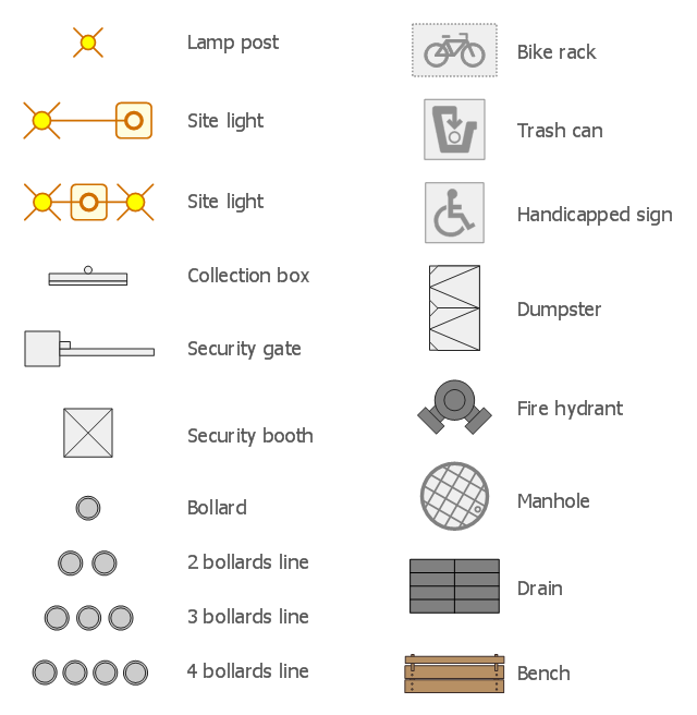
The design elements library Site accessories contains 18 symbols of vehicle access control equipment (tollbooth, tollgate, parking fees payment box), a handicapped sign, outdoor lighting, and garbage receptacles.
"A site plan is an architectural plan, landscape architecture document, and a detailed engineering drawing of proposed improvements to a given lot. A site plan usually shows a building footprint, travelways, parking, drainage facilities, sanitary sewer lines, water lines, trails, lighting, and landscaping and garden elements." [Site plan. Wikipedia]
Use the Site accessories library to design plans, equipment layouts and maps of sites, parking lots, residential and commercial landscapes, parks, yards, plats, outdoor recreational facilities, and irrigation systems using ConceptDraw PRO diagramming and vector drawing software.
The design elements library Site accessories is contained in the Site Plans solution from the Building Plans area of ConceptDraw Solution Park.
- Design elements - Plumbing | Surface Water Drain Symbol
- Plumbing and Piping Plans | Symbol For Water Drain Pipeline
- Design elements - Plumbing | Head Drain Shower Symbols For A Plan
- Fittings Of Water Line And Drainage Line With Symbols
- Drain Pipe Symbol
- Piping Symbols And Fittings
- Design elements - Plumbing | Plumbing Drainage System Symbols
- Water Supply Symbol
- Signs And Symbols Associated With Drainage And Sewage Design
- Drainage Plan Symbols
- Backflow Preventer Symbol
- Schematic Symbols For Water
- What Are Sanitary Symbols
- Hydraulic Symbol Water
- Pipe Fittings Symbol
- Sign Or Symbol Water Fittings
- Plumbing Fittings Symbols
- Interior Design Plumbing - Design Elements | Interior Design Piping ...
- Solenoid Symbol
- Interior Design Piping Plan - Design Elements | Water Separator ...