Mechanical Drawing Symbols

"Directional control valves are one of the most fundamental parts in hydraulic machinery as well and pneumatic machinery. They allow fluid flow into different paths from one or more sources. They usually consist of a spool inside a cylinder which is mechanically or electrically controlled. The movement of the spool restricts or permits the flow, thus it controls the fluid flow. ...
While working with layouts of hydraulic machinery it is cumbersome to draw actual picture of every valve and other components.instead of pictures symbols are used for variety of components in the hydraulic system to highlight the functional aspects. symbol for directional control valve is made of number of square boxes adjacent to each other depending on the number of positions.connections to the valve are shown on these squares by capital letters.usually they are named only in their normal position and not repeated in other positions.actuation system of the valve is also designated in its symbol." [Directional control valve. Wikipedia]
The Mac template "Pneumatic 5-ported 3-position valve" for the ConceptDraw PRO diagramming and vector drawing software is included in the Mechanical Engineering solution from the Engineering area of ConceptDraw Solution Park.
www.conceptdraw.com/ solution-park/ engineering-mechanical
Pneumatic directional control valve

"Directional control valves are one of the most fundamental parts in hydraulic machinery as well and pneumatic machinery. They allow fluid flow into different paths from one or more sources. They usually consist of a spool inside a cylinder which is mechanically or electrically controlled. The movement of the spool restricts or permits the flow, thus it controls the fluid flow. ... Directional control valves can be classified according to: (1) number of ports; (2) number of positions; (3) actuating methods; (4) type of spool." [Directional control valve. Wikipedia]
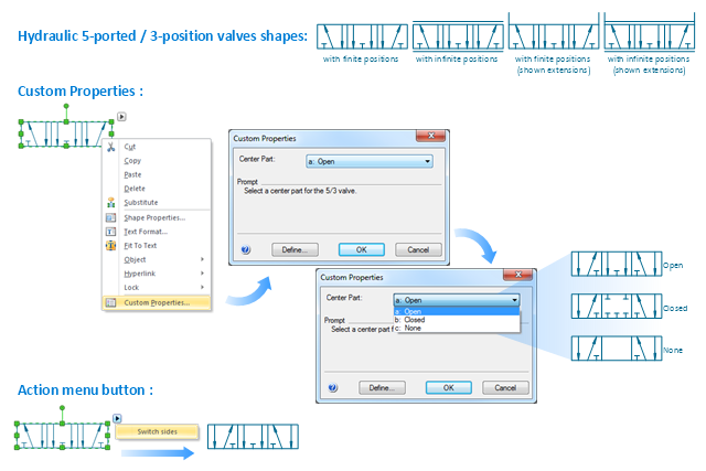
The Windows template "Hydraulic 5-ported 3-position valve" for the ConceptDraw PRO diagramming and vector drawing software is included in the Mechanical Engineering solution from the Engineering area of ConceptDraw Solution Park.
www.conceptdraw.com/ solution-park/ engineering-mechanical
The Windows template "Hydraulic 5-ported 3-position valve" for the ConceptDraw PRO diagramming and vector drawing software is included in the Mechanical Engineering solution from the Engineering area of ConceptDraw Solution Park.
www.conceptdraw.com/ solution-park/ engineering-mechanical
Hydraulic directional control valve
"An air-operated valve is a type of power operated valve that uses air pressure against a piston or diaphragm to produce linear or circular movement to operate a valve. Types are 2-way, 3-way and 4-way. The 2 way air-operated valves can be either normally closed or normally opened." [Air-operated valve. Wikipedia]
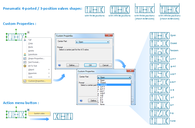
The Windows template "Pneumatic 4-ported 3-position valve" for the ConceptDraw PRO diagramming and vector drawing software is included in the Mechanical Engineering solution from the Engineering area of ConceptDraw Solution Park.
www.conceptdraw.com/ solution-park/ engineering-mechanical
The Windows template "Pneumatic 4-ported 3-position valve" for the ConceptDraw PRO diagramming and vector drawing software is included in the Mechanical Engineering solution from the Engineering area of ConceptDraw Solution Park.
www.conceptdraw.com/ solution-park/ engineering-mechanical
Pneumatic directional control valve
- Mechanical Engineering | Mechanical Drawing Symbols ...
- Mechanical Drawing Symbols | Valves - Vector stencils library ...
- Hydraulic circuits | Design elements - Hydraulic pumps and motors ...
- Mechanical Drawing Symbols | Hydraulic 4-ported 3-position valve ...
- Basic Hydraulic Valve Symbol
- Many Type Of Hydraulic Valve Symbol
- Typical Hydraulic Cylinder Control Schematic
- Hydraulic Valve Symbols And Functions
- Types Of Hydraulic Valve Symbils
- Hydraulic Valve Symbol And Model
- Hydraulic Schematic Valve Symbol
- Hydraulic Valve Symbols Chart
- Design elements - Valves and fittings | Hydraulic Turning Joint Symbol
- Hydraulic circuits | Mechanical Drawing Symbols | Technical ...
- Mechanical Drawing Symbols | Pneumatic 5-ported 3-position valve ...
- Mechanical Drawing Symbols | Directional control valve | Directional ...
- Mechanical Drawing Symbols | Retract resistor check valve ...
- Types Of Hydraulic Symbol Valve
- Pneumatic 5-ported 3-position valve template - Mac | Hydraulic ...
- Mechanical Drawing Symbols | Pneumatic 5-ported 3-position valve ...