Electrical Symbols — Maintenance

The vector stencils library "Transformers and windings" contains 29 element symbols of transformers, windings, couplers, metering devices, transductors, magnetic cores, chokes, and a variometer.
Use it to design the electromechanical device schematics and electronic circuit diagrams.
"A transformer is an electrical device that transfers energy between two circuits through electromagnetic induction. Transformers may be used in step-up or step-down voltage conversion, which 'transforms' an AC voltage from one voltage level on the input of the device to another level at the output terminals. This special function of transformers can provide control of specified requirements of current level as an alternating current source, or it may be used for impedance matching between mismatched electrical circuits to effect maximum power transfer between the circuits.
A transformer most commonly consists of two windings of wire that are wound around a common core to induce tight electromagnetic coupling between the windings. The core material is often a laminated iron core. The coil that receives the electrical input energy is referred to as the primary winding, while the output coil is called the secondary winding.
An alternating electric current flowing through the primary winding (coil) of a transformer generates an electromagnetic field in its surroundings and a varying magnetic flux in the core of the transformer. By electromagnetic induction this magnetic flux generates a varying electromotive force in the secondary winding, resulting in a voltage across the output terminals. If a load impedance is connected across the secondary winding, a current flows through the secondary winding drawing power from the primary winding and its power source." [Transformer. Wikipedia]
"An electromagnetic coil (or simply a "coil") is formed when a conductor is wound around a core or form to create an inductor or electromagnet. When electricity is passed through a coil, it generates a magnetic field. One loop of wire is usually referred to as a turn or a winding, and a coil consists of one or more turns. For use in an electronic circuit, electrical connection terminals called taps are often connected to a coil. Coils are often coated with varnish or wrapped with insulating tape to provide additional insulation and secure them in place. A completed coil assembly with one or more set of coils and taps is often called the windings.
Windings are used in transformers, electric motors, inductors, solenoids, loudspeakers, and many other applications." [Electromagnetic coil. Wikipedia]
The shapes example "Design elements - Transformers and windings" was drawn using the ConceptDraw PRO diagramming and vector drawing software extended with the Electrical Engineering solution from the Engineering area of ConceptDraw Solution Park.
Transformer and winding symbols

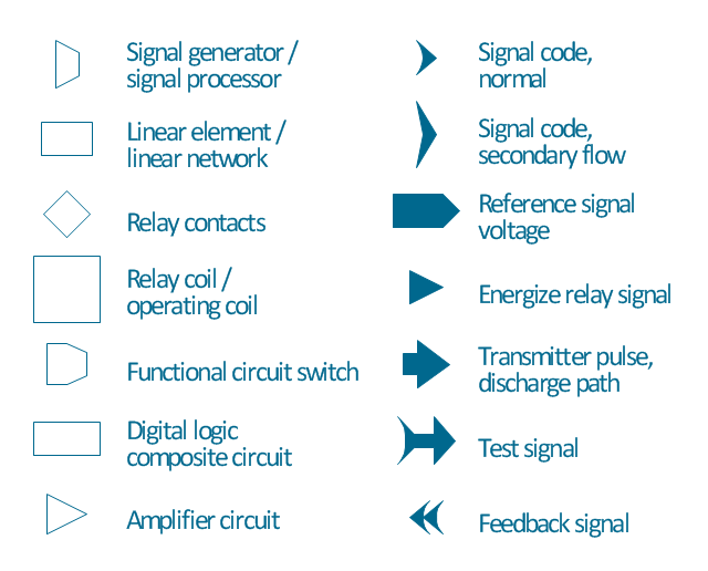
The vector stencils library "Maintenance" contains 14 symbols for maintaining electrical and electronic systems, including test, feedback and reference signals; pulses; relay contacts and coils; and composite and amplifier circuits.
Use these shapes for drawing electronic diagrams in the ConceptDraw PRO diagramming and vector drawing software extended with the Electrical Engineering solution from the Engineering area of ConceptDraw Solution Park.
www.conceptdraw.com/ solution-park/ engineering-electrical
Use these shapes for drawing electronic diagrams in the ConceptDraw PRO diagramming and vector drawing software extended with the Electrical Engineering solution from the Engineering area of ConceptDraw Solution Park.
www.conceptdraw.com/ solution-park/ engineering-electrical
Signal generator

Linear element

Relay contacts

Relay coil

Switch
Composite circuit

Amplifier

Signal code, normal

Signal code, secondary flow

Reference signal

Energize relay signal

Transmitter pulse

Test signal

Feedback

Network Glossary Definition


The vector stencils library "Maintenance" contains 14 symbols for maintaining electrical and electronic systems, including test, feedback and reference signals; pulses; relay contacts and coils; and composite and amplifier circuits.
The symbols example "Design elements - Maintenance" was drawn using the ConceptDraw PRO diagramming and vector drawing software extended with the Electrical Engineering solution from the Engineering area of ConceptDraw Solution Park.
The symbols example "Design elements - Maintenance" was drawn using the ConceptDraw PRO diagramming and vector drawing software extended with the Electrical Engineering solution from the Engineering area of ConceptDraw Solution Park.
Maintenance symbols
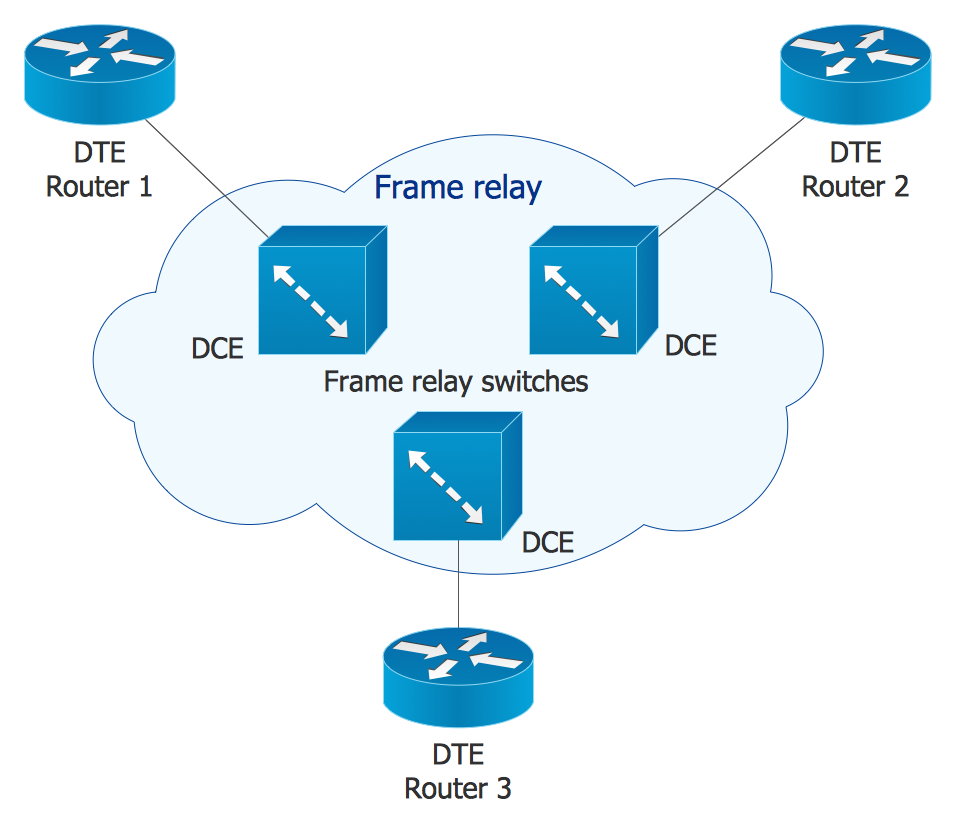
Cisco Network Design. Cisco icons, shapes, stencils, symbols and design elements

The vector stencils library "Maintenance" contains 14 symbols for maintaining electrical and electronic systems, including test, feedback and reference signals; pulses; relay contacts and coils; and composite and amplifier circuits.
The symbols example "Design elements - Maintenance" was drawn using the ConceptDraw PRO diagramming and vector drawing software extended with the Electrical Engineering solution from the Engineering area of ConceptDraw Solution Park.
The symbols example "Design elements - Maintenance" was drawn using the ConceptDraw PRO diagramming and vector drawing software extended with the Electrical Engineering solution from the Engineering area of ConceptDraw Solution Park.
Maintenance symbols
Cisco Network Icons
 Interactive Voice Response Diagrams
Interactive Voice Response Diagrams solution extends ConceptDraw DIAGRAM software with samples, templates and libraries of ready-to-use vector stencils that help create Interactive Voice Response (IVR) diagrams illustrating in details a work of interactive voice response system, the IVR system’s logical and physical structure, Voice-over-Internet Protocol (VoIP) diagrams, and Action VoIP diagrams with representing voice actions on them, to visualize how the computers interact with callers through voice recognition and dual-tone multi-frequency signaling (DTMF) keypad inputs.
Seven Basic Tools of Quality — Quality Control

- Design elements - Transformers and windings | Circuit Symbol For ...
- Magnetic Core Symbol
- Choke Schematic Symbol
- Design elements - Transformers and windings | Electrical Symbols ...
- Symbol Of Winding
- Electrical Symbols , Electrical Diagram Symbols | Design elements ...
- Symbol For Control Transformer
- Design elements - Transformers and windings | How to Convert a ...
- Electrical Choke Symbol
- Electrical Symbols — Transformers and Windings | Design elements ...