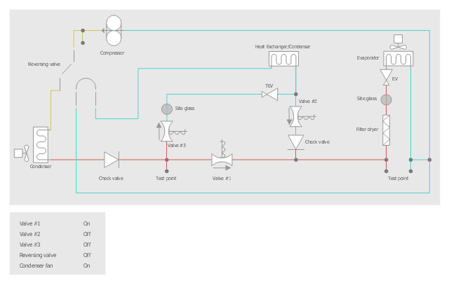
This HVAC schematics sample depicts the house cool mode of central air pool heater. It was drawn on the base of the HVAC schematics in the post "Central Air Pool Heater" from the Nathan Stratton's blog.
"With House Cool Mode, hot gas leaves the compressor runs through the reversing value into the condenser where it condenses into a liquid. Valve #1 is ON so liquid is able to leave the outside unit and run through the filter dryer and site glass into the evaporator upstairs in the house where the liquid flashes into a gas as it passes through the expansion valve and absorbs heat from the air passing through the evaporator. The cold gas travels downstairs and outside to the compressor and the cycle starts all over again." [robotics.net/ projects/ central-air-pool-heater/ ]
The HVAC schematics example "Central air pool heater" was created using the ConceptDraw PRO diagramming and vector drawing software extended with the HVAC Plans solution from the Building Plans area of ConceptDraw Solution Park.
- Interior Design Registers, Drills and Diffusers - Design Elements ...
- Active indirect water heater diagram | Appliances - Vector stencils ...
- Central air pool heater - House cool mode | Active indirect water ...
- House tap water supply | House water heating | House water ...
- Active indirect water heater diagram | House water heating | Flat ...
- Drawing Illustration | CCTV Surveillance System Diagram. CCTV ...
- HVAC control equipment - Vector stencils library | Central air pool ...
- HVAC Plans | How to Create a HVAC Plan | Air handler- HVAC plan ...
- Active indirect water heater diagram | Energy Pyramid Diagram ...
- Draw A Schematics Of Water Cycle
- Heating Drawing Legend
- Ductwork layout | Apartment HVAC plan | House tap water supply ...
- Water cycle diagram | Drawing Illustration | Beauty in nature ...
- Mechanical Drawing Symbols | ConceptDraw Solution Park ...
- HVAC Plans | Central air pool heater | Building Drawing Software for ...
- HVAC Plans | Block diagram - Automotive HVAC system | How to ...
- Design elements - HVAC controls | Security system floor plan ...
- Flats Drawing Plan
- House floor plan | Plumbing and Piping Plans | Interior Design ...
- How to Create a HVAC Plan | Building Drawing Software for Design ...
