Network Printer


Network Layout

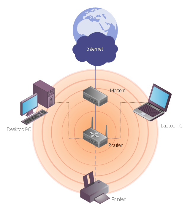
This network diagram sample depicts usage of wireless access point.
"In computer networking, a wireless access point (AP) is a device that allows wireless devices to connect to a wired network using Wi-Fi, or related standards. The AP usually connects to a router (via a wired network) as a standalone device, but it can also be an integral component of the router itself. ...
With the creation of the wireless Access Point (AP), network users are now able to add devices that access the network with few or no cables. An AP normally connects directly to a wired Ethernet connection and the AP then provides wireless connections using radio frequency links for other devices to utilize that wired connection. Most APs support the connection of multiple wireless devices to one wired connection. Modern APs are built to support a standard for sending and receiving data using, these radio frequencies. Those standards, and the frequencies they use are defined by the IEEE. Most APs use IEEE 802.11 standards." [Wireless access point. Wikipedia]
The wireless network diagram example "Wireless access point" was created using the ConceptDraw PRO diagramming and vector drawing software extended with the Wireless Networks solution from the Computer and Networks area of ConceptDraw Solution Park.
Wireless network diagram
The vector stencils library "Network layout floorplan" contain 34 symbol icons for drawing computer network floor plans and communication equipment and cabling layouts.
"Networking hardware may also be known as network equipment or computer networking devices. Units which are the last receiver or generate data are called hosts or data terminal equipment.
All these terms refer to devices facilitating the use of a computer network. Specifically, they mediate data in a computer network. ...
Typically, networking hardware includes gateways, routers, network bridges, switches, hubs, and repeaters. But it also includes hybrid network devices such as multilayer switches, protocol converters, bridge routers, proxy servers, firewalls, network address translators, multiplexers, network interface controllers, wireless network interface controllers, modems, ISDN terminal adapters, line drivers, wireless access points, networking cables and other related hardware.
The most common kind of networking hardware today is a copper-based Ethernet adapter because of its standard inclusion on most modern computer systems. Wireless networking has, however, become increasingly popular, especially for portable and handheld devices.
Other hardware prevalent in computer networking includes data center equipment (such as file servers, database servers and storage areas), network services (such as DNS, DHCP, email, etc.) as well as devices which assure content delivery." [Networking hardware. Wikipedia]
The shapes example "Design elements - Network layout floorplan" was created using the ConceptDraw PRO diagramming and vector drawing software extended with the Network Layout Floor Plans solution from the Computer and Networks area of ConceptDraw Solution Park.
Network layout floor plan symbols

- Network Printer | Network diagrams with ConceptDraw PRO | How to ...
- Network Printer | Physical LAN topology diagram | Mesh Network ...
- Network Printer | Cisco Routers. Cisco icons, shapes, stencils and ...
- Network Printer | Office pictograms - Vector stencils library ...
- Computer Network Diagrams | Network Topologies | Network Printer ...
- Network Printer | Home wireless network diagram | Wireless access ...
- Network Printer | Network Hubs | Network diagrams with ...
- Network Gateway Router | Network Printer | Network Diagram ...
- Network Printer | Cisco Products Additional. Cisco icons, shapes ...
- Network Printer | Network diagrams with ConceptDraw PRO | Local ...
- Desine The Layout Of Lan With 10 Pcs And A Network Printer
- Wireless Networks | Network Printer | Computer Networking Tools ...
- Network Printer | Active Directory Domain Services | Electrical and ...
- Star Network Topology | Network Printer | Cisco Network Design ...
- Personal area (PAN) networks . Computer and Network Examples ...
- Layout Of Lan With 10 Pc And A Network Printer
- Network Printer | Wireless Network Diagram Examples | Network ...
- Network Printer | Mesh Network Topology Diagram | Network Layout ...
- Using Both Wired and Wireless Connections | Network Printer ...
- Network Topologies | Network Printer | Network Gateway Router ...