HelpDesk
How to Create a Plant Layout Design
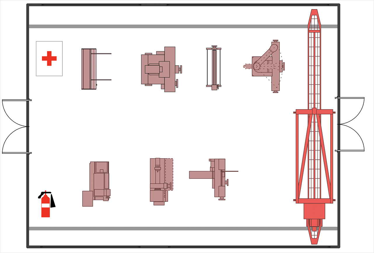
A plant construction process begins from a plant layout stage - an engineering stage used to design, analyze and finally choose the suitable configurations for a manufacturing plant. Plant Layout issues are core to any enterprise and are challenged in all types of manufacturing process. The sufficiency of layout influences the efficiency of subsequent operations. It is an important background for efficient manufacturing and also has a great deal with many questions. Once the place of the plant has been determined, the next important task before the management of the plant is to plan appropriate layout for the enterprise. Plant layout is used to create the most effective physical arrangement of machinery and equipment, with the plant building in such a manner so as to make quickest and cheapest way from a raw material to the shipment of the completed product Making a plan that shows the location of industrial equipment involves many different elements that can be managed using ConThis is a schematic process flow diagram of the processes used in a typical oil refinery.
This process flow diagram (PFD) example was redesigned from the Wikimedia Commons file: RefineryFlow.png. [commons.wikimedia.org/ wiki/ File:RefineryFlow.png]
This file is licensed under the Creative Commons Attribution-Share Alike 3.0 Unported license. [creativecommons.org/ licenses/ by-sa/ 3.0/ deed.en]
"An oil refinery or petroleum refinery is an industrial process plant where crude oil is processed and refined into more useful products such as petroleum naphtha, gasoline, diesel fuel, asphalt base, heating oil, kerosene and liquefied petroleum gas. Oil refineries are typically large, sprawling industrial complexes with extensive piping running throughout, carrying streams of fluids between large chemical processing units. In many ways, oil refineries use much of the technology of, and can be thought of, as types of chemical plants. The crude oil feedstock has typically been processed by an oil production plant. There is usually an oil depot (tank farm) at or near an oil refinery for the storage of incoming crude oil feedstock as well as bulk liquid products.
An oil refinery is considered an essential part of the downstream side of the petroleum industry." [Oil refinery. Wikipedia]
The PFD example "Process flow diagram - Typical oil refinery" was created using the ConceptDraw PRO diagramming and vector drawing software extended with the Chemical and Process Engineering solution from the Chemical and Process Engineering area of ConceptDraw Solution Park.
Bubble diagrams in Landscape Design with ConceptDraw DIAGRAM
Bubble Diagrams are the charts with a bubble presentation of data with obligatory consideration of bubble's sizes. They are analogs of Mind Maps and find their application at many fields, and even in landscape design. At this case the bubbles are applied to illustrate the arrangement of different areas of future landscape design, such as lawns, flowerbeds, playgrounds, pools, recreation areas, etc. Bubble Diagram helps to see instantly the whole project, it is easy for design and quite informative, in most cases it reflects all needed information. Often Bubble Diagram is used as a draft for the future landscape project, on the first stage of its design, and in case of approval of chosen design concept is created advanced detailed landscape plan with specification of plants and used materials. Creation of Bubble Diagrams for landscape in ConceptDraw DIAGRAM software is an easy task thanks to the Bubble Diagrams solution from "Diagrams" area. You can use the ready scanned location plan as the base or create it easy using the special ConceptDraw libraries and templates.- Flow Chart Of Plants
- Process Flow Diagram Symbols | Design elements - Chemical ...
- Plant Layout Plans | Process Flow Diagram Symbols | Chemistry ...
- Plant Layout Plans | Onion Diagram Process Design | Process flow ...
- Process Flow Chart | Plant Design | How to Create a Plant Layout ...
- Gas Plant Process Flow Diagram
- Gas Processing Plant Flow Diagram
- Process Flowchart | Chemistry Drawing Software | Process Flow ...
- Plant Layout Plans | Process Flowchart | Decision Making | Diagram ...
- Power Plant Office Project Management Software Block Diagram
- Block Flow Diagram Of Natural Gas Processing Plant
- Distilling Plant Diagram Showing Valves And Pump
- Piping and Instrumentation Diagram Software | Process Flowchart ...
- Basic Flowchart Symbols and Meaning | Plant Layout Plans | ERD ...
- Flow Chart Of Chemical Distillation Plant
- Flow Chart Of Plant Design Concepts
- Distillery Plant Process Diagram
- Process Flow Diagram Symbols | Process Flowchart | Biology ...
- Petrochemical Industry Wih Help Of Process Flow Diagram
- Process Flow Diagram Symbols | Process Flowchart | Types of ...

-process-flow-diagram---typical-oil-refinery.png--diagram-flowchart-example.png)
