This process flow diagram (PFD) of a typical crude oil distillation unit as used in petroleum crude oil refineries was redrawn from Wikipedia file: Crude Oil Distillation Unit.png. [en.wikipedia.org/ wiki/ File:Crude_ Oil_ Distillation_ Unit.png]
This file is licensed under the Creative Commons Attribution-Share Alike 3.0 Unported license. [creativecommons.org/ licenses/ by-sa/ 3.0/ deed.en]
"An oil refinery or petroleum refinery is an industrial process plant where crude oil is processed and refined into more useful products such as petroleum naphtha, gasoline, diesel fuel, asphalt base, heating oil, kerosene and liquefied petroleum gas. Oil refineries are typically large, sprawling industrial complexes with extensive piping running throughout, carrying streams of fluids between large chemical processing units. In many ways, oil refineries use much of the technology of, and can be thought of, as types of chemical plants. The crude oil feedstock has typically been processed by an oil production plant. There is usually an oil depot (tank farm) at or near an oil refinery for the storage of incoming crude oil feedstock as well as bulk liquid products.
An oil refinery is considered an essential part of the midstream side of the petroleum industry." [en.wikipedia.org/ wiki/ Oil_ refinery]
The process flow diagram (PFD) example "Crude oil distillation" was drawn using the ConceptDraw PRO diagramming and vector drawing software extended with the Chemical and Process Engineering solution from the Chemical and Process Engineering area of ConceptDraw Solution Park.
Process flow diagram (PFD)
-crude-oil-distillation-unit---pfd.png--diagram-flowchart-example.png)
This is a schematic process flow diagram of the processes used in a typical oil refinery.
This process flow diagram (PFD) example was redesigned from the Wikimedia Commons file: RefineryFlow.png. [commons.wikimedia.org/ wiki/ File:RefineryFlow.png]
This file is licensed under the Creative Commons Attribution-Share Alike 3.0 Unported license. [creativecommons.org/ licenses/ by-sa/ 3.0/ deed.en]
"An oil refinery or petroleum refinery is an industrial process plant where crude oil is processed and refined into more useful products such as petroleum naphtha, gasoline, diesel fuel, asphalt base, heating oil, kerosene and liquefied petroleum gas. Oil refineries are typically large, sprawling industrial complexes with extensive piping running throughout, carrying streams of fluids between large chemical processing units. In many ways, oil refineries use much of the technology of, and can be thought of, as types of chemical plants. The crude oil feedstock has typically been processed by an oil production plant. There is usually an oil depot (tank farm) at or near an oil refinery for the storage of incoming crude oil feedstock as well as bulk liquid products.
An oil refinery is considered an essential part of the downstream side of the petroleum industry." [Oil refinery. Wikipedia]
The PFD example "Process flow diagram - Typical oil refinery" was created using the ConceptDraw PRO diagramming and vector drawing software extended with the Chemical and Process Engineering solution from the Chemical and Process Engineering area of ConceptDraw Solution Park.
Process Flow Diagram (PFD)
-process-flow-diagram---typical-oil-refinery.png--diagram-flowchart-example.png)
"Business process improvement (BPI) is a systematic approach to help an organization optimize its underlying processes to achieve more efficient results. ...
An organization is only as good as its processes. To be able to make the necessary changes in an organization, one needs to understand the key processes of the company. Rummler and Brache suggested a model for running a Process Improvement and Management project (PI&M), containing the following steps:
1. Identify the process to be improved (based on a critical business issue): The identification of key processes can be a formal or informal exercise. The management team might select processes by applying a set of criteria derived from strategic and tactical priorities, or process selection is based on obvious performance gaps. It is important is to select the process(es) which have the greatest impact on a competitive advantage or customer requirement.
2. Develop the objective(s) for the project based on the requirements of the process: The focus might be on quality improvement, productivity, cost, customer service or cycle time. The goal is however always the same; to get the key process under control.
3. Select the members of the cross-functional team: A horizontal (cross-functional) analysis is carried out by a team composed of representatives of all functions involved in the process. While a consultant or in-house staff person can do the job, the quality of the analysis and the commitment to change is far greater with a cross-functional team.
4. Document the current process by creating a flowchart or "organization map": Describe the process regarding the Organizational level, the Process level and the Job/ Performer level according to Rummler. Develop a cross-functional process map for the process.
5. Identify "disconnects" in the process: “Disconnections” are everything that inhibit the efficiency and effectiveness of the process. The identification should be categorized into the three levels: The Organizational level, the Process level and the Job/ Performer level.
6. Recommend changes (organizational, in the process or in its execution): Categorize and prioritize the main problems and possibilities, evaluate alternative solutions. Develop a cross-functional process map for the recommended process.
7. Establish process and sub-process measures: The process measures should reflect the objectives of the project.
8. Implement the improvements." [Business process improvement. Wikipedia]
The opportunity flow chart example "Replacing engine oil" was created using the ConceptDraw PRO diagramming and vector drawing software extended with the Cross-Functional Flowcharts solution from the Business Processes area of ConceptDraw Solution Park.
Opportunity flowchart

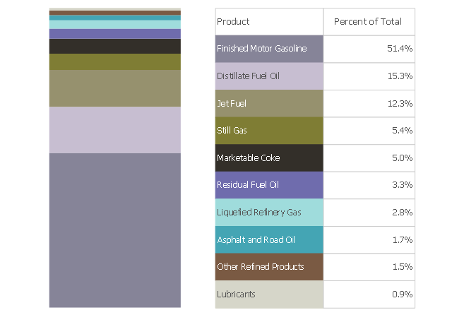
This divided bar chart sample shows the petroleum products yielded from 1 barrel of crude oil in California in 2004. It was drawn using data from the chart on the California Energy Almanac website. [energyalmanac.ca.gov/ gasoline/ whats_ in_ barrel_ oil.html]
"Petroleum products are useful materials derived from crude oil (petroleum) as it is processed in oil refineries. Unlike petrochemicals, which are a collection of well-defined usually pure chemical compounds, petroleum products are complex mixtures. The majority of petroleum is converted to petroleum products, which includes several classes of fuels.
According to the composition of the crude oil and depending on the demands of the market, refineries can produce different shares of petroleum products. The largest share of oil products is used as "energy carriers", i.e. various grades of fuel oil and gasoline. These fuels include or can be blended to give gasoline, jet fuel, diesel fuel, heating oil, and heavier fuel oils. Heavier (less volatile) fractions can also be used to produce asphalt, tar, paraffin wax, lubricating and other heavy oils. Refineries also produce other chemicals, some of which are used in chemical processes to produce plastics and other useful materials. Since petroleum often contains a few percent sulfur-containing molecules, elemental sulfur is also often produced as a petroleum product. Carbon, in the form of petroleum coke, and hydrogen may also be produced as petroleum products. The hydrogen produced is often used as an intermediate product for other oil refinery processes such as hydrocracking and hydrodesulfurization." [Petroleum product. Wikipedia]
The chart example "Petroleum products yielded from one barrel of crude oil" was created using the ConceptDraw PRO diagramming and vector drawing software extended with the Divided Bar Diagrams solution from the Graphs and Charts area of ConceptDraw Solution Park.
Divided bar chart
The vector stencils library "Heating equipment" contains 42 symbols of regenerators, intercoolers, heaters, and condensers.
Use these shapes for drawing cooling systems, heat recovery systems, thermal, heat transfer and mechanical design, and process flow diagrams (PFD) in the ConceptDraw PRO software extended with the Chemical and Process Engineering solution from the Chemical and Process Engineering area of ConceptDraw Solution Park.
www.conceptdraw.com/ solution-park/ engineering-chemical-process
Heat exchanger 3

Heat exchanger 1

Heat exchanger 2

Tube bundle, floating head

U-Tube bundle

Tube bundle

Shell and tube

Kettle reboiler

Plate type

Finned tube

Double pipe type

Oil burner

Boiler

Fired heater

Cooling tower 2

Cooling tower 1

Cooling tower 3

Condenser

Automatic stoker

Refrigerator

Direct refrigerator

Indirect refrigerator

Evaporative condenser

Condenser (air cooled)
-heating-equipment---vector-stencils-library.png--diagram-flowchart-example.png)
Oil separator

Chilling evaporator

Air cooling evaporator

Extractor hood (slot)
-heating-equipment---vector-stencils-library.png--diagram-flowchart-example.png)
Extractor hood (open)
-heating-equipment---vector-stencils-library.png--diagram-flowchart-example.png)
Autoclave (propeller)
-heating-equipment---vector-stencils-library.png--diagram-flowchart-example.png)
Autoclave (anchor)
-heating-equipment---vector-stencils-library.png--diagram-flowchart-example.png)
Autoclave (helical)
-heating-equipment---vector-stencils-library.png--diagram-flowchart-example.png)
Autoclave with motor (helical)
-heating-equipment---vector-stencils-library.png--diagram-flowchart-example.png)
Autoclave with motor (anchor)
-heating-equipment---vector-stencils-library.png--diagram-flowchart-example.png)
Autoclave with motor (propeller)
-heating-equipment---vector-stencils-library.png--diagram-flowchart-example.png)
Fan blades horizontal

Fan blades vertical

Fan blades (4)
-heating-equipment---vector-stencils-library.png--diagram-flowchart-example.png)
Triple fan blades

Air-blown cooler

Condenser

Heater / Cooler

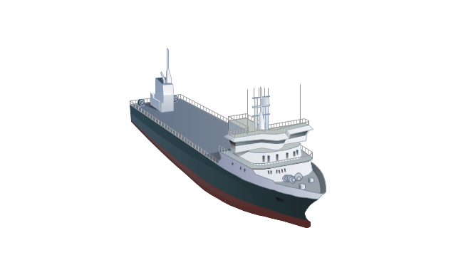
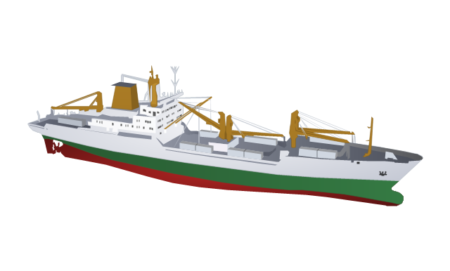
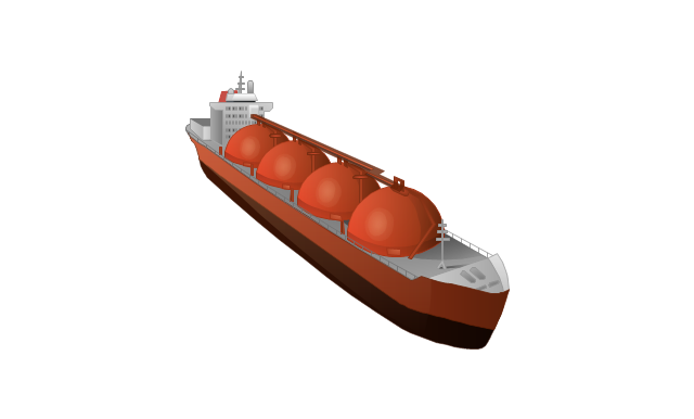
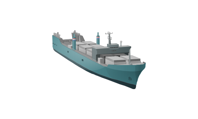
The vector stencils library "Watercraft" contains 28 clip art images for creating ship transport illustrations, presentation slides, infographics and webpages using the ConceptDraw PRO diagramming and vector drawing software.
"The term watercraft covers a range of different vehicles including ships, boats, hovercraft and submarines, and differs from a simple device that merely floats, such as a log raft. ...
Usually the purposes behind watercraft designs and skills are for seafaring education or leisure activities, fishing and resource extraction, transportation of cargo or passengers, and for conducting combat or salvage operations. In general, the purpose of a water vehicle identifies its utility with a maritime industry sub-sector." [Watercraft. Wikipedia]
The vector stencils library "Watercraft" is included in the Aerospace and Transport solution from the Illustrations area of ConceptDraw Solution Park.
www.conceptdraw.com/ solution-park/ illustrations-aerospace-transport
Boat

Motorboat
Yacht

Sailing yacht

Motor yacht

Passenger vessel

Sailing ship

Passenger ship
Regular ship
Tugboat
Oil ship
Dry cargo ship
Dry cargo vessel
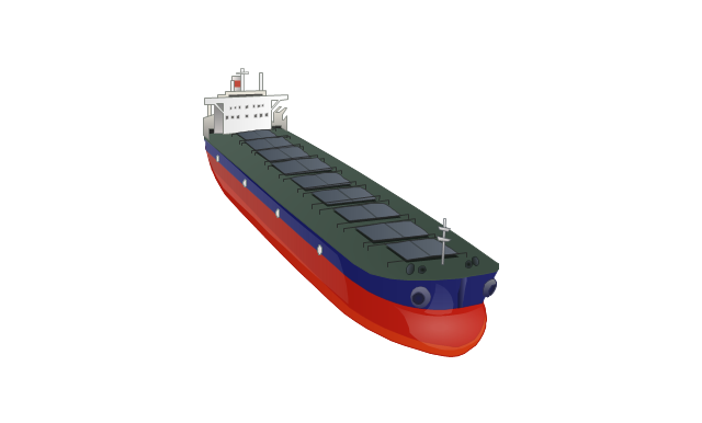
Capesize bulk-carrier
Handysize bulk-carrier
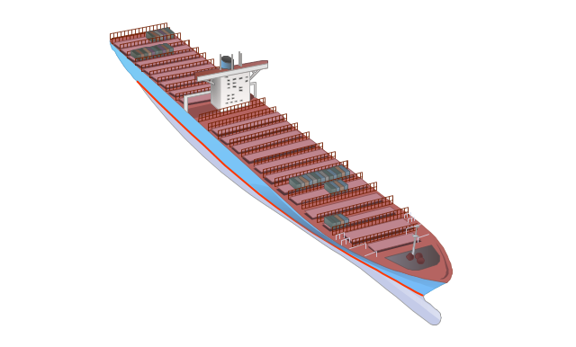
Container ship
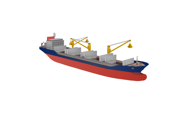
Multipurpose ship
Reefer
Oil tanker

Reefer vessel
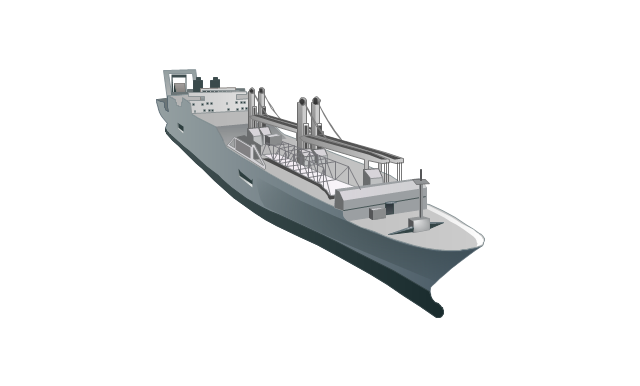
Gas ship
Lighter aboard ship
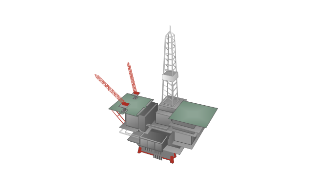
Offshore oil platform
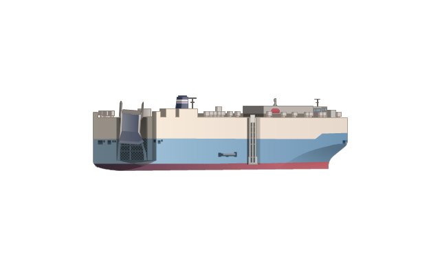
Car carrier
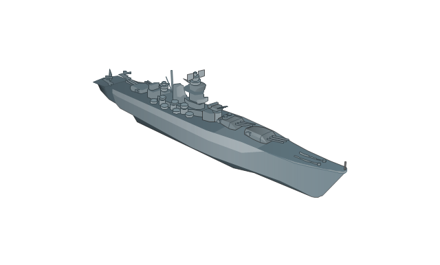
Battleship
Submarine
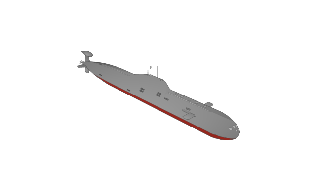
Submarine
Container ship
The vector stencils library "Laboratory equipment" contains 31 clipart icons of chemical laboratory equipment and labware.
Use these shapes for drawing part assembly and mounting schemes of glassware apparatus in chemical experiment diagrams and illustrations in the ConceptDraw PRO diagramming and vector drawing software extended with the Chemistry solution from the Science and Education area of ConceptDraw Solution Park.
Use these shapes for drawing part assembly and mounting schemes of glassware apparatus in chemical experiment diagrams and illustrations in the ConceptDraw PRO diagramming and vector drawing software extended with the Chemistry solution from the Science and Education area of ConceptDraw Solution Park.
Vigreux distillation column

Hirsch funnel

Oil bath

Steam bath

Thermometer

Tap (valve)
--laboratory-equipment---vector-stencils-library.png--diagram-flowchart-example.png)
Vacuum adaptor

Liebig condenser (long)
-laboratory-equipment---vector-stencils-library.png--diagram-flowchart-example.png)
Liebig condenser (short)
-laboratory-equipment---vector-stencils-library.png--diagram-flowchart-example.png)
Water faucet

Büchner flask

Stemless funnel

Stemmed funnel

Separatory funnel

Heating mantle

Hot plate

Gas tap

Folded filter paper

Y-Adaptor

Claisen adapter

Bunsen burner

Büchner funnel

Erlenmeyer flask, 25ml

Round-bottom flask, 50ml

Round-bottom flask, 250ml

Beaker 100ml, filled

Beaker 100ml, empty

Beaker 500ml, filled

Beaker 500ml, empty

Erlenmeyer flask 250ml, filled

Erlenmeyer flask 250ml, empty

Process Flow Diagram Symbols

This PFD sample was redesigned from the Wikipedia file: NaturalGasCondensate.png.
"This is a schematic flow diagram of a typical facility for separating and recovering liquid condensate from raw natural gas."
[en.wikipedia.org/ wiki/ File:NaturalGasCondensate.png]
"Natural-gas condensate is a low-density mixture of hydrocarbon liquids that are present as gaseous components in the raw natural gas produced from many natural gas fields. It condenses out of the raw gas if the temperature is reduced to below the hydrocarbon dew point temperature of the raw gas.
The natural gas condensate is also referred to as simply condensate, or gas condensate, or sometimes natural gasoline because it contains hydrocarbons within the gasoline boiling range. Raw natural gas may come from any one of three types of gas wells:
(1) Crude oil wells - Raw natural gas that comes from crude oil wells is called associated gas. This gas can exist separate from the crude oil in the underground formation, or dissolved in the crude oil.
(2) Dry gas wells - These wells typically produce only raw natural gas that does not contain any hydrocarbon liquids. Such gas is called non-associated gas.
(3) Condensate wells - These wells produce raw natural gas along with natural gas liquid. Such gas is also non-associated gas and often referred to as wet gas." [Natural-gas condensate. Wikipedia]
The process flow diagram example "Natural gas condensate - PFD" was drawn using the ConceptDraw PRO software extended with the Chemical and Process Engineering solution from the Chemical and Process Engineering area of ConceptDraw Solution Park.
Process flow diagram (PFD)
-natural-gas-condensate---pfd.png--diagram-flowchart-example.png)
The vector stencils library "Pumps" contains 82 symbols of pumps, compressors, fans, turbines, and power generators.
Use these icons to design pumping systems, air and fluid compression systems, and industrial process diagrams in the ConceptDraw PRO software extended with the Chemical and Process Engineering solution from the Chemical and Process Engineering area of ConceptDraw Solution Park.
www.conceptdraw.com/ solution-park/ engineering-chemical-process
In-line pump

In-line pump 2

Positive displacement

Centrifugal pump (arrows)
-pumps---vector-stencils-library.png--diagram-flowchart-example.png)
Centrifugal pump

Rotary pump 1

Rotary pump 2

Proportioning pump

Pump vacuum

Pump positive displacement

Pump piston

Pump liquid ring

Pump oil-sealed rotary (single)
-pumps---vector-stencils-library.png--diagram-flowchart-example.png)
Pump oil-sealed rotary (multi)
-pumps---vector-stencils-library.png--diagram-flowchart-example.png)
Pump roots

Pump gas ballast

Pump turbo molecular

Pump general

Pump centrifugal

Pump positive displacement 2

Pump gear

Pump screw

Pump helical rotor

Pump reciprocating

Pump diaphragm

Pump liquid jet

Pump centrifugal 2

Pump diaphragm 2

Pump gear 2

Pump general 2

Pump helical rotor 2

Pump reciprocating 2

Pump screw 2

Compressor general

Compressor container

Compressor rotary

Compressor screw

Compressor reciprocating

Compressor ejector

Compressor general 2

Compressor liquid ring

Compressor positive displacement

Compressor reciprocating 2

Compressor reciprocating diaphragm

Compressor roller vane

Compressor rotary 2

Compressor screw 2

Compressor turbo

Compressor general 3

Compressor reciprocating 3

Compressor reciprocating diaphragm 2

Compressor roller vane 2

Compressor rotary 3

Compressor screw 3

Rotary compressor

Motor driven turbine

Compressor (center line)
-pumps---vector-stencils-library.png--diagram-flowchart-example.png)
Compressor

Turbine

Turbine (center line)
-pumps---vector-stencils-library.png--diagram-flowchart-example.png)
Reciprocating pump/compressor

Reciprocating pump 2

Fan general

Fan radial

Fan axial

Fan general 2

Fan radial 2

Fan axial 2

Centrifugal fan 2 (center circle)
-pumps---vector-stencils-library.png--diagram-flowchart-example.png)
Centrifugal fan

Axial flow fan supply

Axial flow fan exhaust

Axial flow fan exhaust wall-type

Axial flow fan supply wall-type

Axial flow fan 2

Ejector / injector

Spray

Shower

Fan blades horizontal

Fan blades vertical

Fan blades (4)
-pumps---vector-stencils-library.png--diagram-flowchart-example.png)
Triple fan blades

Geo Map - Asia - Saudi Arabia

Watercraft - Design Elements

Basic Flowchart Examples

The vector stencils library "Resources and energy" contains 19 clipart images for drawing illustrations on resources and energy.
"Natural resources occur naturally within environments that exist relatively undisturbed by humanity, in a natural form. A natural resource is often characterized by amounts of biodiversity and geodiversity existent in various ecosystems.
Natural resources are derived from the environment. Some of them are essential for our survival while most are used for satisfying our wants. Natural resources may be further classified in different ways.
Natural resources are materials and components (something that can be used) that can be found within the environment. Every man-made product is composed of natural resources (at its fundamental level). A natural resource may exist as a separate entity such as fresh water, and air, as well as a living organism such as a fish, or it may exist in an alternate form which must be processed to obtain the resource such as metal ores, oil, and most forms of energy." [Natural resource. Wikipedia]
The clip art example "Resources and energy - Vector stencils library" was created in ConceptDraw PRO diagramming and vector drawing software using the Manufacturing and Maintenance solution from the Illustration area of ConceptDraw Solution Park.
Human resources

Batteries

Wind turbine

Transmission tower

Natural gas burner

Solar panel

Lightning

Ionizing radiation hazard sign

High voltage symbol

Atom

Incandescent light bulb

Oil barrels

Power station

Wood

Perpetuum mobile

Hydroelectric dam

Liquefied petroleum gas

Natural gas

Minecart with coal

This process flow diagram (PFD) example shows an amine treating system for the removal of gaseous hydrogen sulfide from gas streams. It is used in oil refineries and chemical plants. This PFD sample was redesigned from the Wikimedia Commons file: AmineTreating.png. [commons.wikimedia.org/ wiki/ File:AmineTreating.png]
This file is licensed under the Creative Commons Attribution-Share Alike 3.0 Unported license. [creativecommons.org/ licenses/ by-sa/ 3.0/ deed.en]
"Amine gas treating, also known as gas sweetening and acid gas removal, refers to a group of processes that use aqueous solutions of various alkylamines (commonly referred to simply as amines) to remove hydrogen sulfide (H2S) and carbon dioxide (CO2) from gases. It is a common unit process used in refineries, and is also used in petrochemical plants, natural gas processing plants and other industries.
Processes within oil refineries or chemical processing plants that remove hydrogen sulfide are referred to as "sweetening" processes because the odor of the processed products is improved by the absence of hydrogen sulfide. An alternative to the use of amines involves membrane technology. Membranes are attractive since no reagents are consumed.
Many different amines are used in gas treating:
Diethanolamine (DEA),
Monoethanolamine (MEA),
Methyldiethanolamine (MDEA),
Diisopropanolamine (DIPA),
Aminoethoxyethanol (Diglycolamine) (DGA).
The most commonly used amines in industrial plants are the alkanolamines DEA, MEA, and MDEA. These amines are also used in many oil refineries to remove sour gases from liquid hydrocarbons such as liquified petroleum gas (LPG)." [Amine gas treating. Wikipedia]
The PFD example "Amine treating unit schematic diagram" was drawn using the ConceptDraw PRO diagramming and vector drawing software extended with the Chemical and Process Engineering solution from the Chemical and Process Engineering area of ConceptDraw Solution Park.
Process Flow Diagram (PFD)
-amine-treating-unit-schematic-diagram.png--diagram-flowchart-example.png)
- Crude oil distillation unit - PFD | Process flow diagram (PFD ...
- Process flow diagram - Typical oil refinery | Natural gas condensate ...
- Pfd Chemical Engineering Software
- Process flow diagram - Typical oil refinery | Basic Flowchart Symbols ...
- Process flow diagram - Typical oil refinery | Crude oil distillation unit ...
- Crude oil distillation unit - PFD | Process Flow Diagram Symbols ...
- Crude oil distillation unit - PFD | Process Flow Diagram | Process ...
- Crude oil distillation unit - PFD | Petroleum products yielded from ...
- Crude oil distillation unit - PFD | Process flow diagram - Typical oil ...
- Schematic Flow Diagram Of A Typical Crude Oil Distillation Unit
- Crude oil distillation unit - PFD | The Drawing Of Crude Distilation
- Process Flowchart | Electrical Symbols, Electrical Diagram Symbols ...
- Petroleum products yielded from one barrel of crude oil | Process ...
- Process Flow Diagram | Crude oil distillation unit - PFD | Distillation ...
- Heating equipment - Vector stencils library | Oil Burner Chemical ...
- Sample Oil And Gas Process Flow Diagram In Pdf
- Process flow diagram - Typical oil refinery | Chemical and Process ...
- Watercraft - Design Elements | Crude oil distillation unit - PFD ...
- Crude oil distillation unit - PFD | Process Engineering | Process Flow ...
- Process Flow Diagram Symbols | Crude oil distillation unit - PFD ...