Network Diagram Software. LAN Network Diagrams. Physical Office Network Diagrams


 Network Layout Floor Plans
Network Layout Floor Plans solution extends ConceptDraw DIAGRAM software functionality with powerful tools for quick and efficient documentation the network equipment and displaying its location on the professionally designed Network Layout Floor Plans. Never before creation of Network Layout Floor Plans, Network Communication Plans, Network Topologies Plans and Network Topology Maps was not so easy, convenient and fast as with predesigned templates, samples, examples and comprehensive set of vector design elements included to the Network Layout Floor Plans solution. All listed types of plans will be a good support for the future correct cabling and installation of network equipment.
Network Diagram Software Logical Network Diagram

Pyramid Diagram

How To use House Electrical Plan Software


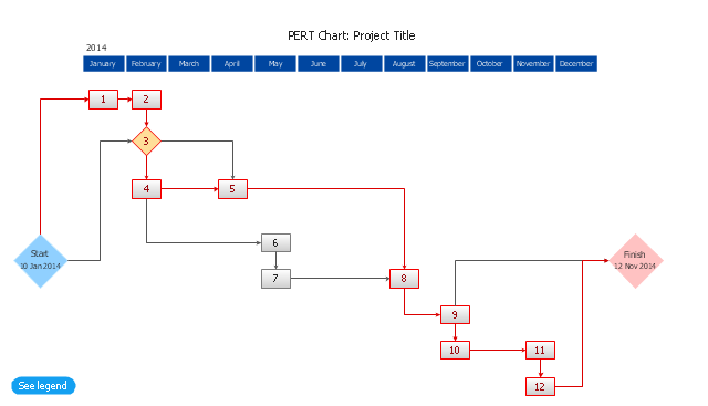
The PERT chart shows the logical connections and consequence of a set of tasks. PERT charts the time period for problem solving and the implementation plan for all activities along the critical path. The PERT chart is also known as a precedence diagram or project network diagram.
"The Program (or Project) Evaluation and Review Technique, commonly abbreviated PERT, is a statistical tool, used in project management, that is designed to analyze and represent the tasks involved in completing a given project. ...
PERT is a method to analyze the involved tasks in completing a given project, especially the time needed to complete each task, and to identify the minimum time needed to complete the total project.
PERT was developed primarily to simplify the planning and scheduling of large and complex projects. ...
A network diagram can be created by hand or by using diagram software. There are two types of network diagrams, activity on arrow (AOA) and activity on node (AON). Activity on node diagrams are generally easier to create and interpret." [Program Evaluation and Review Technique. Wikipedia]
The PERT chart is one of the Seven Management and Planning Tools (7 MP tools, Seven New Quality Tools).
The PERT chart template for the ConceptDraw PRO diagramming and vector drawing software is included in the solution "Seven Management and Planning Tools" from the Management area of ConceptDraw Solution Park.
PERT chart template
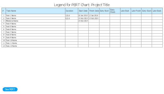
Legend
 Business Processes Area
Solutions of Business Processes area extend ConceptDraw DIAGRAM software with samples, templates and vector stencils libraries for drawing business process diagrams and flowcharts for business process management.
 Basic Bar Graphs
This solution enhances ConceptDraw DIAGRAM (or later) with templates, samples and a library of vector stencils for drawing Bar Graphs.
HelpDesk
How To Present a Business Process Model

Basic Flowchart Symbols and Meaning


- How To Interpret Network Diagram
- Basic Network Diagram | Fully Connected Network Topology ...
- Interpret An Engineering Drawing Circuit Network Diagram
- Interpret The Architecture Of Cable Tv Network Diagram
- Draw And Interpret A Wiring Diagram To A Named Farm Building
- Draw And Interpret A Wiring Diagram Of A Farm Office
- Hotel Network Topology Diagram . Hotel Guesthouse WiFi Network ...
- School Network Diagram With Explanation
- Network diagrams with ConceptDraw PRO | How to Draw a ...
- Network Printer | Network Diagram Software Physical Network ...
- Network Diagram
- Network Diagram Software LAN Network Diagrams & Diagrams for
- Logical Network Diagrams
- Computer Network Diagrams | Local area network (LAN). Computer ...
- Draw And Interpret Electrical Wiring Diagram Of A Name Farm ...
- How to Draw a Computer Network Diagrams | Network Diagram ...
- Computer Network Diagrams | How to Draw a Computer Network ...
- Network Solution Diagram With Explantion
- Network Diagram Software Physical Network Diagram | Network ...
- Physical Lan Diagrams