"The symbols and conventions used in welding documentation are specified in national and international standards such as ISO 2553 Welded, brazed and soldered joints -- Symbolic representation on drawings and ISO 4063 Welding and allied processes -- Nomenclature of processes and reference numbers. The US standard symbols are outlined by the American National Standards Institute and the American Welding Society and are noted as "ANSI/ AWS".
In engineering drawings, each weld is conventionally identified by an arrow which points to the joint to be welded. The arrow is annotated with letters, numbers and symbols which indicate the exact specification of the weld. In complex applications, such as those involving alloys other than mild steel, more information may be called for than can comfortably be indicated using the symbols alone. Annotations are used in these cases." [Symbols and conventions used in welding documentation. Wikipedia]
The example chart "Elements of welding symbol" is redesigned using the ConceptDraw PRO diagramming and vector drawing software from the Wikipedia file: Elements of a welding symbol.PNG.
[en.wikipedia.org/ wiki/ File:Elements_ of_ a_ welding_ symbol.PNG]
The diagram example "Elements location of a welding symbol" is contained in the Mechanical Engineering solution from the Engineering area of ConceptDraw Solution Park.
Welding joint symbol chart

Electrical Symbols, Electrical Diagram Symbols

The vector stencils library "HR department" contains 50 workflow symbols.
Use this department icon set to draw your HR process flowcharts, workflow diagrams and infographics with the ConceptDraw PRO diagramming and vector drawing software.
The HR pictograms library "HR department" is included in the HR Flowcharts solution from the Management area of ConceptDraw Solution Park.
Accounting

Accounts payable

Accounts receivable

Audit

Bank

Board of directors

Career center

Copy center
Customer service operator

Customer service technician

Data center

Delivery

Design

Devices management

Distribution

Distribution 2
Employee

Engineering
Facilities

Finance

Human resource

Information services

Information systems

International division

International marketing

International sales

Inventory
Legal department

Mail room

Mail service

Management

Manufacturing

Marketing

Motorpool

Online service

Packaging

Payroll

Publications

Purchasing

Quality assurance

Receiving

Reception

Research and development

Scales

Sales growth

Security

Shipping
Suppliers

Telecommunication

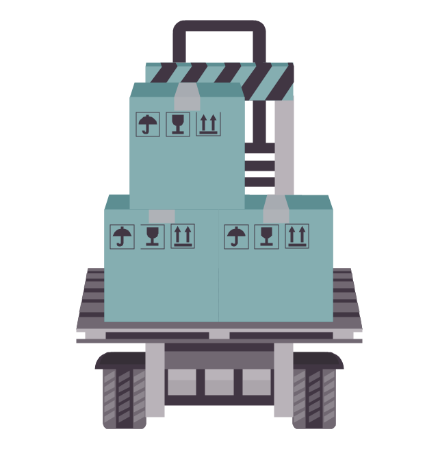
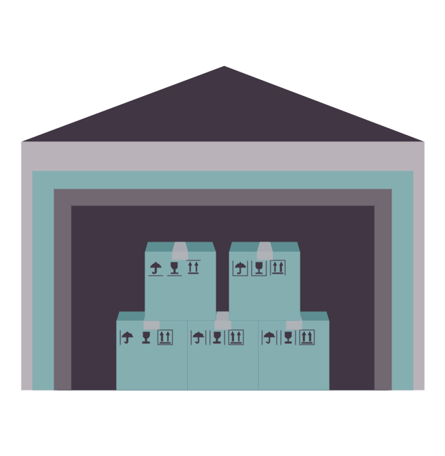
Warehouse
IDEF0 standard with ConceptDraw DIAGRAM

- Elements location of a welding symbol | Welding symbols | Design ...
- Welding symbols | Elements location of a welding symbol | Design ...
- Elements location of a welding symbol | Welding symbols | Elements ...
- Welding Symbols Wiki
- Elements location of a welding symbol | Aws Vs Iso Weld Symbols
- Elements location of a welding symbol | Elements location of a ...
- Welding Symbols Iso
- Elements location of a welding symbol | Welding symbols | Software ...
- Welding symbols
- Elements location of a welding symbol | Welding symbols | Butt weld ...