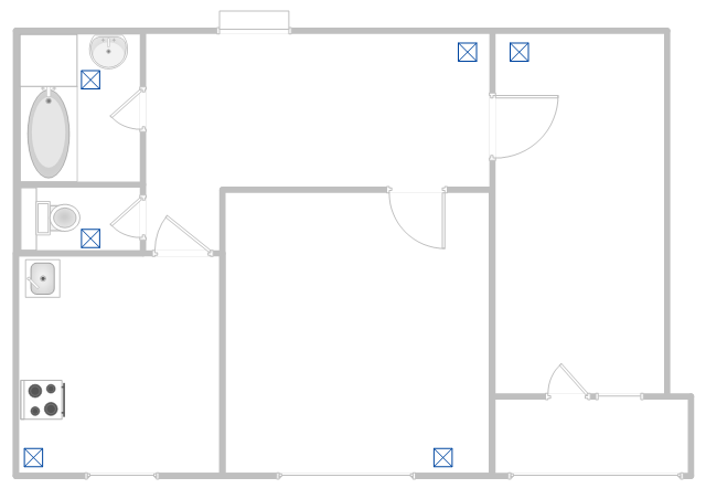
This apartment HVAC (Heating, Ventilating and Air Conditioning) plan shows the layout of exhaust ventilation duct outlet diffusers.
"Ventilation is the intentional introduction of outside air into a space. Ventilation is mainly used to control indoor air quality by diluting and displacing indoor pollutants; it can also be used for purposes of thermal comfort or dehumidification when the introduction of outside air will help to achieve desired indoor psychrometric conditions.
The intentional introduction of outside air can be categorized as either mechanical ventilation, or natural ventilation. Mechanical ventilation uses fans to drive the flow of outside air into a building. This may be accomplished by pressurization (in the case of positively pressurized buildings), or by depressurization (in the case of exhaust ventilation systems). Many mechanically ventilated buildings use a combination of both, with the ventilation being integrated into the HVAC system." [Ventilation (architecture). Wikipedia]
The floor plan example "Apartment HVAC plan" was created using the ConceptDraw DIAGRAM diagramming and vector drawing software extended with the HVAC Plans solution from the Building Plans area of ConceptDraw Solution Park.
Floor plan
This HVAC floor plan sample shows the ventilation duct system layout.
"Ducts are used in heating, ventilation, and air conditioning (HVAC) to deliver and remove air. The needed airflows include, for example, supply air, return air, and exhaust air. Ducts commonly also deliver ventilation air as part of the supply air. As such, air ducts are one method of ensuring acceptable indoor air quality as well as thermal comfort.
A duct system is also called ductwork. Planning (laying out), sizing, optimizing, detailing, and finding the pressure losses through a duct system is called duct design." [Duct (flow). Wikipedia]
The HVAC floor plan example "Ductwork layout" was created using the ConceptDraw DIAGRAM diagramming and vector drawing software extended with the HVAC Plans solution from the Building Plans area of ConceptDraw Solution Park.
HVAC floor plan

 Floor Plans
Construction, repair and remodeling of the home, flat, office, or any other building or premise begins with the development of detailed building plan and floor plans. Correct and quick visualization of the building ideas is important for further construction of any building.
Piping and Instrumentation Diagram Software

Fire Evacuation Plan Template

- How To Place Ducts In Toilets Detail Plan
- Ductwork layout | HVAC Plans | Ventilation system layout | How To ...
- Ductwork layout | Apartment HVAC plan | School HVAC plan | Toilet ...
- School HVAC plan | Lecture theatre | Floor Plans | School Toilet Plan
- Apartment HVAC plan | HVAC Plans | Building Design Package ...
- Ductwork layout | HVAC Plans | House ventilation | Duct In House Plan
- How To Show Ventilating Systems On Floor Plans
- Wedding Floor Plan | Bathroom - Vector stencils library | Design ...
- Ductwork layout | HVAC Plans | Design elements - HVAC ductwork ...
- HVAC Plans | How to Create a HVAC Plan | Air handler- HVAC plan ...