 HVAC Plans
Use HVAC Plans solution to create professional, clear and vivid HVAC-systems design plans, which represent effectively your HVAC marketing plan ideas, develop plans for modern ventilation units, central air heaters, to display the refrigeration systems for automated buildings control, environmental control, and energy systems.
This HVAC schematics sample was redesigned from the Wikimedia Commons file: Ventilation unit with heat pump & ground heat exchanger.png. [commons.wikimedia.org/ wiki/ File:Ventilation_ unit_ with_ heat_ pump_ %26_ ground_ heat_ exchanger.png]
This file is licensed under the Creative Commons Attribution-Share Alike 3.0 Unported license. [creativecommons.org/ licenses/ by-sa/ 3.0/ deed.en]
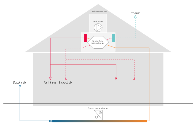
"Heat recovery ventilation, also known as HRV, mechanical ventilation heat recovery, or MVHR, is an energy recovery ventilation system using equipment known as a heat recovery ventilator, heat exchanger, air exchanger, or air-to-air heat exchanger which employs a counter-flow heat exchanger (countercurrent heat exchange) between the inbound and outbound air flow. HRV provides fresh air and improved climate control, while also saving energy by reducing heating (and cooling) requirements.
Energy recovery ventilators (ERVs) are closely related, however ERVs also transfer the humidity level of the exhaust air to the intake air." [Heat recovery ventilation. Wikipedia]
The HVAC schematics example "Ventilation unit with heat pump and ground heat exchanger" was created using the ConceptDraw PRO diagramming and vector drawing software extended with the HVAC Plans solution from the Building Plans area of ConceptDraw Solution Park.
This file is licensed under the Creative Commons Attribution-Share Alike 3.0 Unported license. [creativecommons.org/ licenses/ by-sa/ 3.0/ deed.en]
"Heat recovery ventilation, also known as HRV, mechanical ventilation heat recovery, or MVHR, is an energy recovery ventilation system using equipment known as a heat recovery ventilator, heat exchanger, air exchanger, or air-to-air heat exchanger which employs a counter-flow heat exchanger (countercurrent heat exchange) between the inbound and outbound air flow. HRV provides fresh air and improved climate control, while also saving energy by reducing heating (and cooling) requirements.
Energy recovery ventilators (ERVs) are closely related, however ERVs also transfer the humidity level of the exhaust air to the intake air." [Heat recovery ventilation. Wikipedia]
The HVAC schematics example "Ventilation unit with heat pump and ground heat exchanger" was created using the ConceptDraw PRO diagramming and vector drawing software extended with the HVAC Plans solution from the Building Plans area of ConceptDraw Solution Park.
HVAC schematics
 Office Layout Plans
Office layouts and office plans are a special category of building plans and are often an obligatory requirement for precise and correct construction, design and exploitation office premises and business buildings. Designers and architects strive to make office plans and office floor plans simple and accurate, but at the same time unique, elegant, creative, and even extraordinary to easily increase the effectiveness of the work while attracting a large number of clients.
 Fire and Emergency Plans
This solution extends ConceptDraw software with samples, templates and design elements for drawing the Fire and Emergency Plans.
This sport field plan sample was designed on the base of the Wikipedia file: VolleyballCourt.svg. [en.wikipedia.org/ wiki/ File:VolleyballCourt.svg]
This file is licensed under the Creative Commons Attribution-Share Alike 3.0 Unported license. [creativecommons.org/ licenses/ by-sa/ 3.0/ deed.en]
"Volleyball is a team sport in which two teams of six players are separated by a net. Each team tries to score points by grounding a ball on the other team's court under organized rules. It has been a part of the official program of the Summer Olympic Games since 1964. ...
The court dimensions.
A volleyball court is 18 m (59 ft) long and 9 m (29.5 ft) wide, divided into 9 m × 9 m halves by a one-meter (40-inch) wide net. The top of the net is 2.43 m (8 ft 0 in) above the center of the court for men's competition, and 2.24 m (7 ft 4 in) for women's competition, varied for veterans and junior competitions.
The minimum height clearance for indoor volleyball courts is 7 m (23 ft), although a clearance of 8 m (26 ft) is recommended.
A line 3 m (9.84 ft) from and parallel to the net is considered the "attack line". This "3 meter" (or "10-foot") line divides the court into "back row" and "front row" areas (also back court and front court). These are in turn divided into 3 areas each: these are numbered as follows, starting from area "1", which is the position of the serving player.
After a team gains the serve (also known as siding out), its members must rotate in a clockwise direction, with the player previously in area "2" moving to area "1" and so on, with the player from area "1" moving to area "6".
The team courts are surrounded by an area called the free zone which is a minimum of 3 meters wide and which the players may enter and play within after the service of the ball. All lines denoting the boundaries of the team court and the attack zone are drawn or painted within the dimensions of the area and are therefore a part of the court or zone. If a ball comes in contact with the line, the ball is considered to be "in". An antenna is placed on each side of the net perpendicular to the sideline and is a vertical extension of the side boundary of the court. A ball passing over the net must pass completely between the antennae (or their theoretical extensions to the ceiling) without contacting them." [Volleyball. Wikipedia]
The sport field plan example "Volleyball court dimensions" was created using the ConceptDraw PRO diagramming and vector drawing software extended with the Sport Field Plans solution from the Building Plans area of ConceptDraw Solution Park.
Sport field plan

 Floor Plans
Construction, repair and remodeling of the home, flat, office, or any other building or premise begins with the development of detailed building plan and floor plans. Correct and quick visualization of the building ideas is important for further construction of any building.
 Cafe and Restaurant Floor Plans
Restaurants and cafes are popular places for recreation, relaxation, and are the scene for many impressions and memories, so their construction and design requires special attention. Restaurants must to be projected and constructed to be comfortable and e
The vector stencils library "Cable TV" contains 64 symbols of cable TV network equipment.
Use these shapes for drawing CATV system design floor plans, network topology diagrams, wiring diagrams and cabling layout schemes in the ConceptDraw PRO diagramming and vector drawing software.
The vector stencils library "Cable TV" is included in the Electric and Telecom Plans solution from the Building Plans area of ConceptDraw Solution Park.
Output Directional Tap 1

Output Directional Tap 2

Output Directional Tap 3

Output Directional Tap 4

Output Directional Tap 5

2-way Splitter

3-way Splitter

4-way Splitter

AC Power Block

Bond

Down Guy

Building Guy and Anchor

Rock Guy with Anchor

Down Guy with Anchor

Pole-to-Pole Guy

Sidewalk Down Guy with Anchor

Sidewalk Down Guy

Slack Span Messenger Wire

Tensioned Messenger Wire w/out cable

Tensioned Messenger Wire

Ground

Joint Usage (Power & Telephone Pole)
-cable-tv---vector-stencils-library.png--diagram-flowchart-example.png)
Joint Usgae Pole with Transformer

Strut

Tree Guy with Anchor

Push Brace (smaller pole in actual relative position)
-cable-tv---vector-stencils-library.png--diagram-flowchart-example.png)
Extension Arm

Built CATV Pole

Proposed CATV Pole

Directional Tap 1

Directional Tap 2

Manhole

Telephone Pole

Riser Pole

Vault Handheld

Fixed Equalizer

Fixed Flat Attenuators

Other Supporting Structures

Pedestal - Underground Routing

Power Pole

Direct Buried Underground Routing

Duct Line Underground Routing

Line Terminations

2-Way Optical Splice Location

3-Way Optical Splice Location

4-Way Optical Splice Location

> 4-Way Optical Splice Location

Optical Amplifier

Cable AC Power Combiner

Optical Fiber Cable

Optical Connector

Wavelength Demultiplexer

Wavelength Multiplexer

Optical Transmitter

Optical Transmitter

Optical Node

Optical Splitter

Headend (Signal Processing)
-cable-tv---vector-stencils-library.png--diagram-flowchart-example.png)
Node

Primary Hub

Secondary Hub

Coaxial Splice

Power Supply

Variable Equalizer

- Floor Plans | Ground Plan And Equipment Needed In An ...
- Ground Plan And Equipment Needed At Hotel
- Ground Plan
- Ventilation unit with heat pump and ground heat exchanger | HVAC ...
- Plant Layout Plans | Factory layout floor plan | Emergency Plan ...
- Factory layout floor plan | Plant Layout Plans | Bar Diagrams for ...
- Industrial Building Ground Floor Plan
- Symbol On Ground Floor Plan
- Gym and Spa Area Plans | How to Draw a Floor Plan for SPA in ...
- Gym and Spa Area Plans | Gym Floor Plan | Gym equipment layout ...
- How To Create Restaurant Floor Plan in Minutes | Seating Plans ...
- Ground Floor Plan Of Factory
- Ventilation unit with heat pump and ground heat exchanger | HVAC ...
- Lighting and switch layout
- Mini Hotel Floor Plan . Floor Plan Examples | Hotel Floorplan | Hotel ...
- How To use House Electrical Plan Software | Electrical Drawing ...
- Blow-through unit ventilator - HVAC plan | Ventilation unit with heat ...
- Smoke alarm equipment layout floor plan | Electrical and telecom ...
- Ground Floor Plan For Industry
- Ground Floor Plan With Hvac