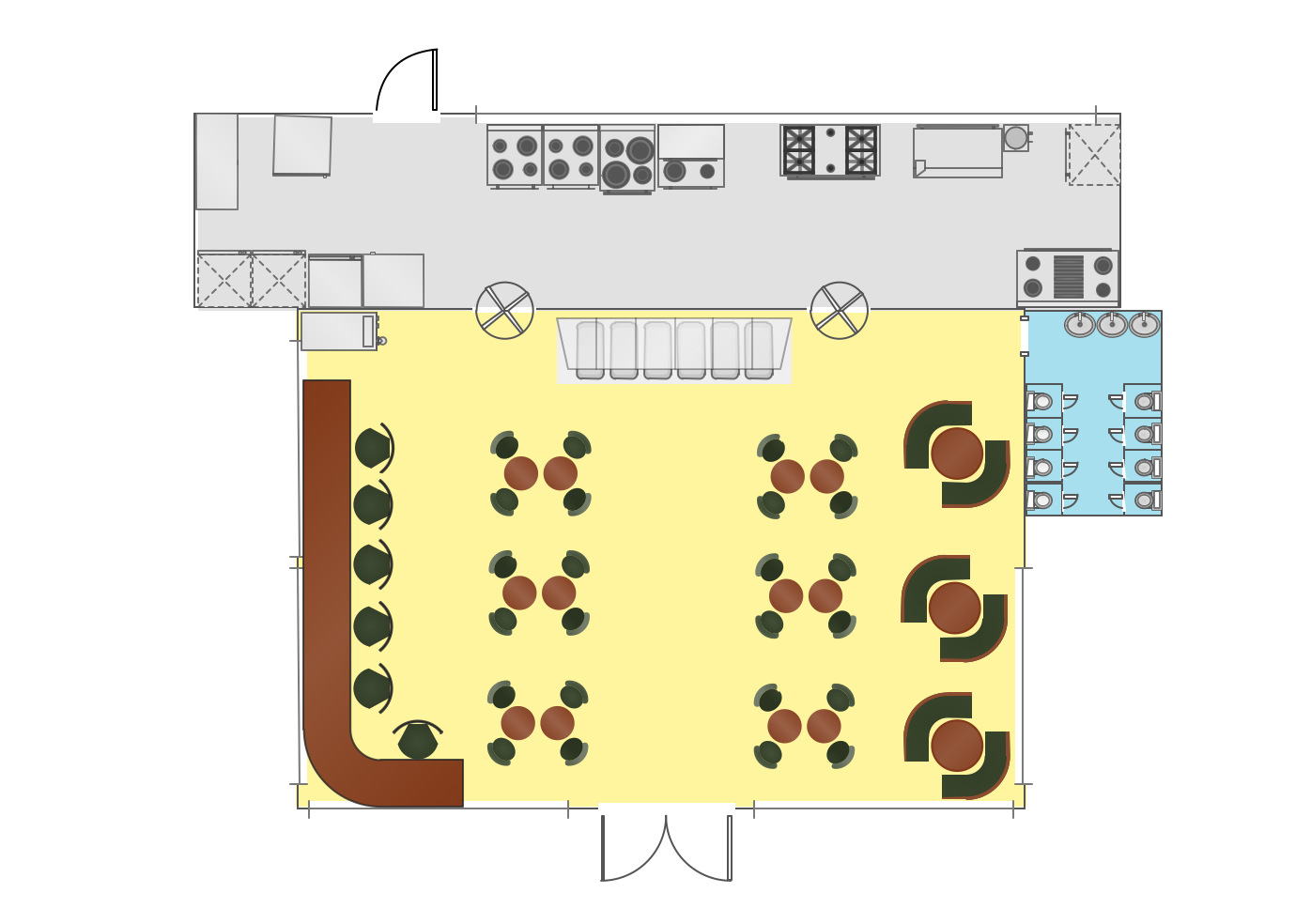
Hotel Floorplan

Interior Design
Network Diagram Software Home Area Network
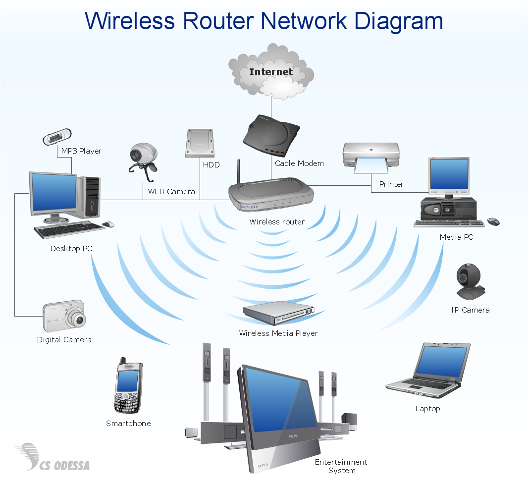

"Physical topology refers to the placement of the network's various components, including device location and cable installation...
The shape of the cabling layout used to link devices is called the physical topology of the network. This refers to the layout of cabling, the locations of nodes, and the interconnections between the nodes and the cabling. The physical topology of a network is determined by the capabilities of the network access devices and media, the level of control or fault tolerance desired, and the cost associated with cabling or telecommunications circuits." [Network topology. Wikipedia]
The LAN cabling layout floorplan example "Local network physical topology floor plan" was created using the ConceptDraw PRO diagramming and vector drawing software extended with the Network Layout Floor Plans solution from the Computer and Networks area of ConceptDraw Solution Park.
LAN cabling layout floorplan

- Design A Well Structured Floor Plan Of Salon With Labels To
- A Well Structured Floor Plan Business With Labels For A Security
- A Well Structured Floor Plan Of Business Examples
- Well Structured Floor Plan For The Business
- Cafe and Restaurant Floor Plans | How To Draw A Water Closet And ...
- How to Create a Floor Plan Using ConceptDraw PRO | How to ...
- How To use House Electrical Plan Software | How To use Building ...
- Small Office Floor Plan Samples
- Floor Plan With Computer Networks
- Floor Plan Of Fire Equipment