Network Diagram Examples
Network diagram is a chart which represents nodes and connections between them in computer network or any telecommunication network, it is a visual depiction of network architecture, physical or logical network topology. There are used common icons for the Network diagrams design, such as icons of various network appliances, computer devices, routers, clouds, peripheral devices, digital devices, etc. Network diagrams can represent networks of different scales (LAN level, WAN level) and detailization. ConceptDraw DIAGRAM diagramming software enhanced with Computer Network Diagrams solution from Computer and Networks area includes huge collection of computer and network templates, design objects and stencils, and numerous quantity of Network diagram examples and samples, among them: Basic Computer Network Diagrams, Communication Network Diagram, Wireless Router Network Diagram, LAN Topology Diagram, Computer Network System Design Diagram, Mobile Satellite Communication Network, Web-based Network Diagram, Hybrid Network Diagram, and many others.
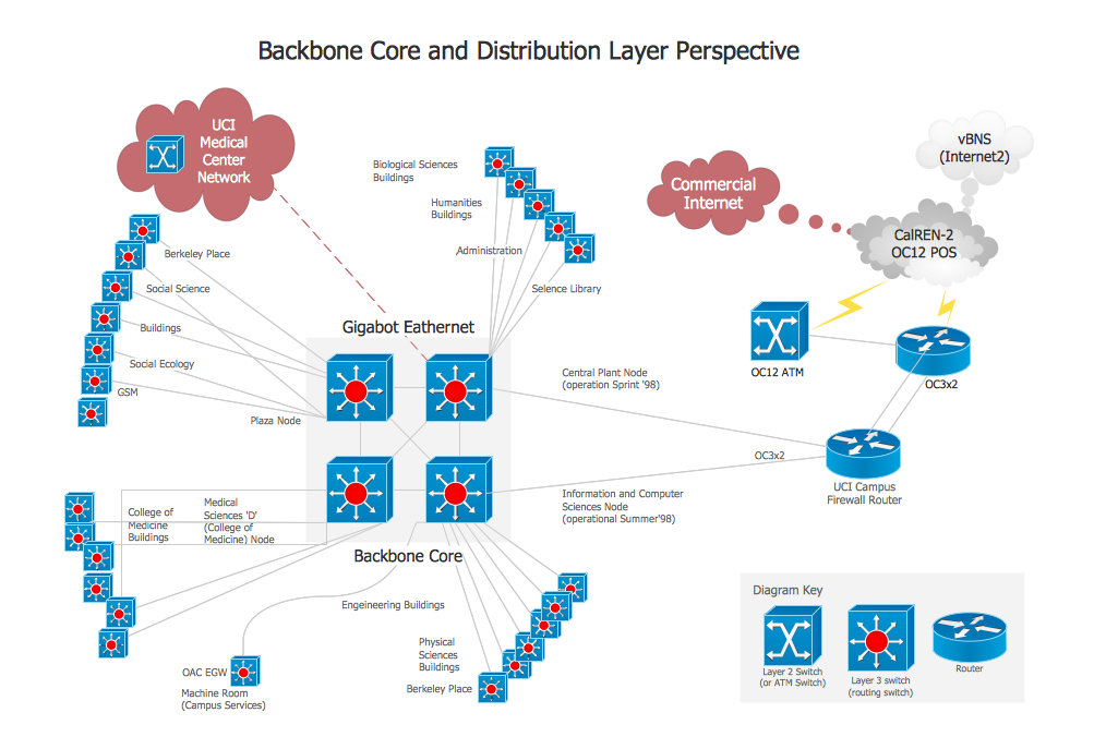
Network Diagram Software Backbone Network
ConceptDraw - Perfect Network Diagramming Software with examples of Backbone Network Diagrams. ConceptDraw Network Diagram is ideal for network engineers and network designers who need to draw Backbone Network diagrams.
This Active Directory network diagram example depicts types of groups and people assignment rules.
Architecture groups in a Windows Active Directory 2003:
(1) The arrow indicates "may be a member of."
(2) Dotted: Functionality limited to Windows 2003 (without the Windows 2000 compatibility).
(3) Red: Setting possible, but not recommended.
It was drawn on the base of Wikimedia Commons file: AD2003.JPG. [commons.wikimedia.org/ wiki/ File:AD2003.JPG]
This file is licensed under the Creative Commons Attribution-Share Alike 3.0 Unported license. [creativecommons.org/ licenses/ by-sa/ 3.0/ deed.en]
The Active Directory network diagram example "Tree and Forest (Full Trust)" was created using the ConceptDraw PRO diagramming and vector drawing software extended with the Active Directory Diagrams solution from the Computer and Networks area of ConceptDraw Solution Park.
HelpDesk
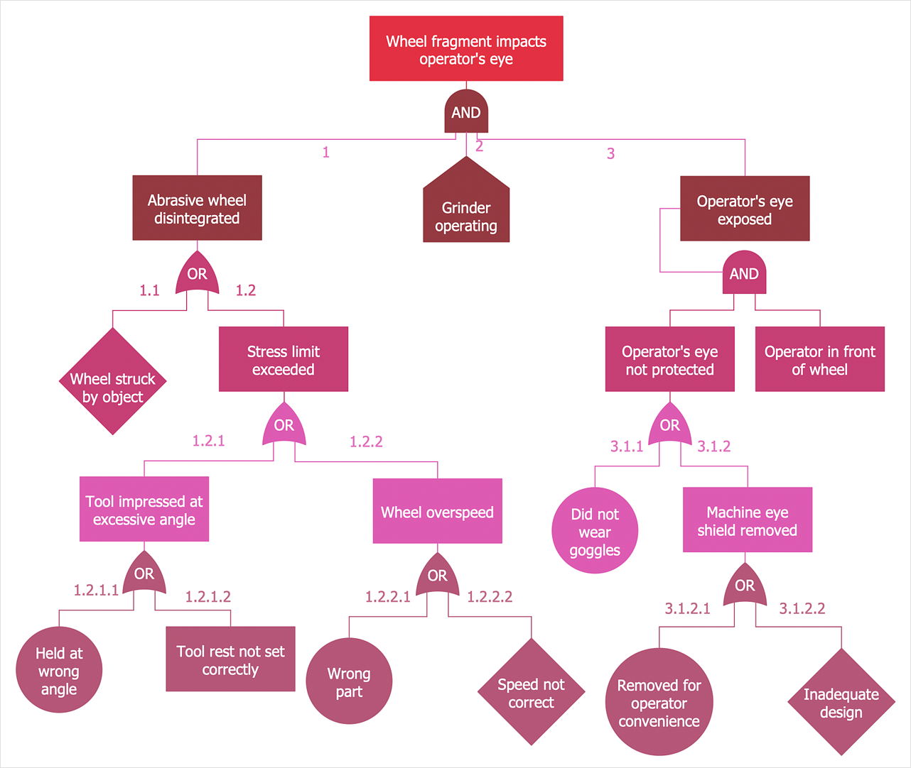
How to Create a Fault Tree Analysis Diagram (FTD)
Fault Tree Diagram is a logic diagram that shows the state of an entire system in a relationship of the conditions of its elements. Fault Tree Diagram is used to analyze the probability of functional system failures and safety accidents. ConceptDraw DIAGRAM allows you to create professional Fault Tree Diagrams using the basic FTD symbols. An FTD visualizes a model of the processes within a system that can lead to the unlikely event. A fault tree diagrams are created using standard logic symbols. The basic elements in a fault tree diagram are gates and events.- Tree Network Topology Diagram | Fully Connected Network ...
- Fully Connected Network Topology Diagram | Network Topologies ...
- Wireless Network Topology | Star Network Topology | Hotel Network ...
- Fully Connected Network Topology Diagram | Network Diagram ...
- Network Topologies | Fully Connected Network Topology Diagram ...
- Wide area network (WAN) topology. Computer and Network ...
- Tree Network Topology Diagram | Fault Tree Analysis Example ...
- Personal area (PAN) networks. Computer and Network Examples ...
- Bus Network Topology | Star Network Topology | Tree Network ...
- Campus Area Networks (CAN). Computer and Network Examples ...
- Network Tree Example
- Local area network (LAN). Computer and Network Examples ...
- Example Of Network Tree
- Star Network Topology | Tree Network Topology Diagram | Hybrid ...
- Network Diagram Examples | WLAN | Network Topology Graphical ...
- Network Topologies | Network Diagram Examples | Active Directory ...
- Example Of Network Tree Of Mindmap
- Trees Diagrams Example
- Give Example Of Network Tree Diagram
- Network Tree Examples


---active-directory-network-diagram.png--diagram-flowchart-example.png)
