HelpDesk
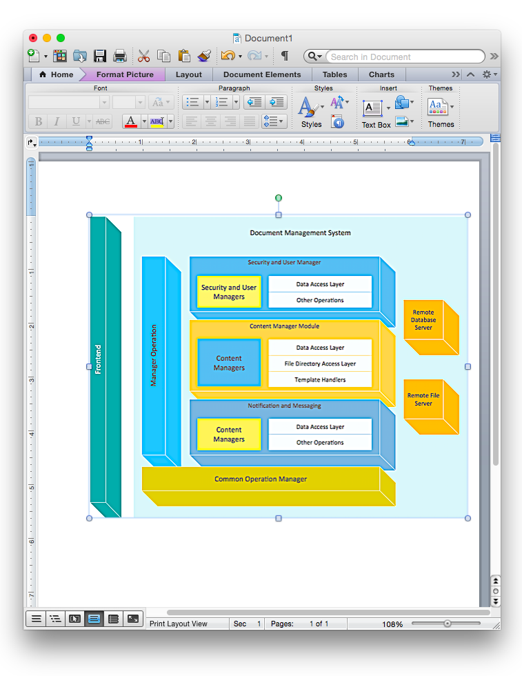
How to Add a Block Diagram to a MS Word ™ Document Using ConceptDraw PRO
Block diagram consists from graphic blocks. Blocks are connected by lines or arrows. Block diagrams are used to show the relationship between parts of some systems. It can be used for the development of new systems or to improve existing ones. The structure of block diagram gives a high-level overview of the major components of the system, as well as the important relationships. Using the block diagrams, you can more effectively present the business data contained in your MS Word documents. ConceptDraw PRO allows you to easily create block diagrams and then insert them into a MS Word document.HelpDesk
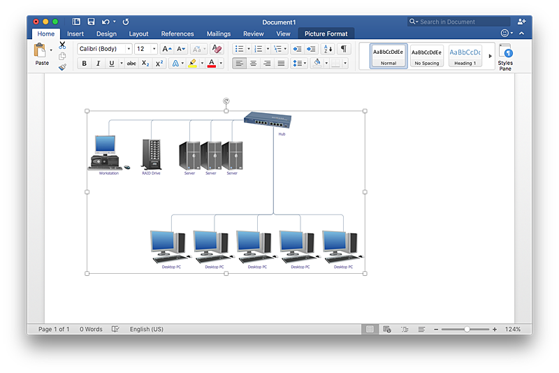
How to Add a Network Diagram to a MS Word Document Using ConceptDraw PRO
Effective management of the computer network of any size includes the creation and maintenance of the network documentation package. Computer network diagrams may be the part of the network documentation that is often presented as MS Word document. Network diagrams describing the topology of the network and equipment installed in the network, are the essential part of this package. ConceptDraw PRO provides network administrators with ability to easily create computer network diagrams and then insert them into a MS Word document.HelpDesk
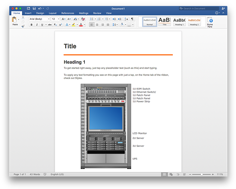
How to Add a Rack Diagram to a MS Word Document Using ConceptDraw PRO
Rack Diagram depicts the structure of network equipment installation, and provides network administrator with the base to support electronic equipment, power, cooling, and cable management. ConceptDraw PRO allows you to easily create diagram that will help to detail the type of rack equipment that best fits your needs and then lets you to insert the scheme of rack configuration into the network documentation pack. ConceptDraw PRO allows you to easily create rack configuration diagrams and then insert them into a MS Word document.HelpDesk
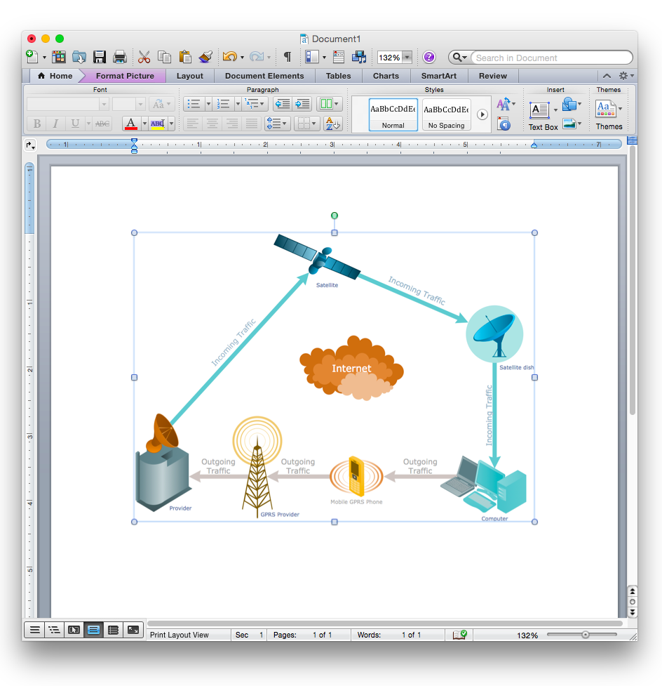
How to Add a Telecommunication Network Diagram to a MS Word Document Using ConceptDraw PRO
ConceptDraw PRO allows you to easily create telecom network diagrams and then insert them into a MS Word document.HelpDesk
How to Draw a Chemical Process Flow Diagram
Process Flow Diagram widely used in modeling of processes in the chemical industry. A Chemical Process Flow diagram (PFD) is a specialized type of flowchart. With the help of Chemical Process Flow Diagram engineers can easily specify the general scheme of the processes and chemical plant equipment. Chemical Process Flow Diagram displays the real scheme of the chemical process, the relationship between the equipment and the technical characteristics of the process. Chemical Process Flow Diagram illustrates the connections between the basic equipment as well as the overall structure of pipelines and other supporting equipment. The purpose of the PFD is to build the image of the basic idea of the chemical process. ConceptDraw PRO together with its Chemical and Process Engineering solution delivers the possibility to design Chemical Process Flow diagrams. It is designed for chemical industry engineers and designers.HelpDesk
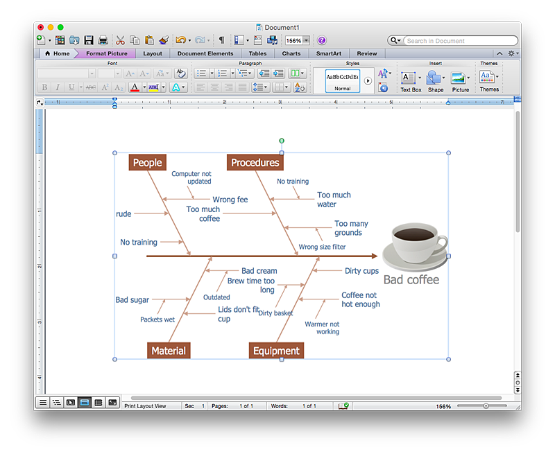
How to Add a Fishbone (Ishikawa) Diagram to a MS Word Document Using ConceptDraw PRO
The ability to create a fishbone (Ishikawa) Diagram is supported by the ConceptDraw Fishbone Diagram solution. ConceptDraw PRO allows you to easily create a fishbone diagrams and then insert them into a MS Word document.HelpDesk
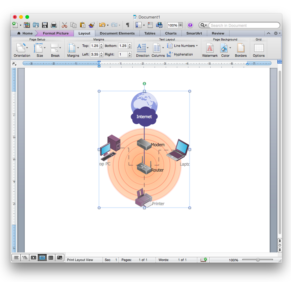
How to Add a Wireless Network Diagram to a MS Word Document Using ConceptDraw PRO
ConceptDraw PRO allows you to easily create wireless computer network diagrams and then insert them into a MS Word document.HelpDesk
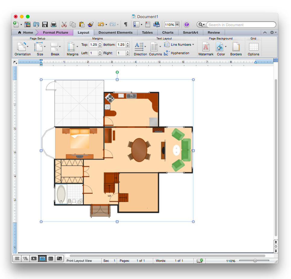
How to Add a Floor Plan to a MS Word Document Using ConceptDraw PRO
ConceptDraw PRO allows you to easily create floor plans of any complexity and then insert them into a MS Word document.
 Chemical and Process Engineering
This chemical engineering solution extends ConceptDraw PRO v.9.5 (or later) with process flow diagram symbols, samples, process diagrams templates and libraries of design elements for creating process and instrumentation diagrams, block flow diagrams (BFD
HelpDesk
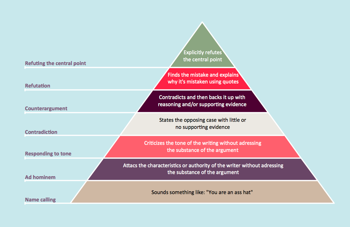
How to Draw a Pyramid Diagram in ConceptDraw PRO
Pyramid diagram (triangle diagram) is used to represent data, which have hierarchy and basics. Due to the triangular form of diagram, each pyramid section has a different width. The width of the segment shows the level of its hierarchy. Typically, the top of the pyramid is the data that are more important than the base data. Pyramid scheme can be used to show proportional and hierarchical relationships between some logically related items, such as departments within an organization, or successive elements of any process. This type of diagram is often used in marketing to display hierarchical related data, but it can be used in a variety of situations. ConceptDraw PRO allows you to make a pyramid diagram, quickly and easily using special libraries.- How To Draw Block Diagram In Word
- How To Draw Physics Diagrams In Word
- How To Draw Fault Tree In Word
- Chemical Process Chart Template Word
- How To Draw A Cycle Diagram In Word
- Draw An Er Diagram Using Word
- Process Flowchart | Process Flow Diagram Symbols | How to Draw a ...
- Chemical and Process Engineering | How to Draw a Chemical ...
- How To Draw Logic Gate In Ms Word
- How to Add a Cross-Functional Flowchart to an MS Word Document ...
- Wireless Network Diagram Examples | Wireless Networks | How To ...
- Draw Flowcharts With Word And Powerpoint
- How To Draw Entity Relationship Diagrams On Ms Word
- How To Draw Block Diagram In Microsoft Powerpoint
- Bubble Diagrams | How To Create a Bubble Chart | Electrical ...
- How To Draw Complete Diagram Using Power
- How to Add a Block Diagram to a MS Word ™ Document Using ...
- Mechanical Drawing Symbols | Process Flow Diagram Symbols ...
- Process Flowchart | Bar Chart Template for Word | Context Diagram ...
- Physics Symbols | Physics Diagrams | Chemical and Process ...
