 Mechanical Engineering
This solution extends ConceptDraw PRO v.9 mechanical drawing software (or later) with samples of mechanical drawing symbols, templates and libraries of design elements, for help when drafting mechanical engineering drawings, or parts, assembly, pneumatic,
A simple hydraulic schematic showing apparatus for testing the strength of a hydraulic hose splice.
Water enters through normally closed solenoid valve (1) and passes through intake flow meter (2) to high pressure pump (4). Intake water pressure is monitored by pressure gauge (3). The hose to be tested connects between pump (4) and normally open solenoid activated drain valve (7). To test the hose, pump drive motor (5) is turned on, the solenoid of drain valve (7) is activated, closing the valve, and the pump is run to pressurize the hose. Test pressure is monitored by gauge (6). When the test is complete or the hose fails, the solenoid of drain valve (7) is deactivated, opening valve and discharging water, depressurizing the system. All components are operated electrically by a remote control circuit so that the operator may perform the test from a protected location, monitoring it with a camera and video monitor.
This hydraulic schematic example was redrawn using ConceptDraw PRO diagramming and vector drawing software from the Wikimedia Commons file: Hydraulic schematic.jpg.
[commons.wikimedia.org/ wiki/ File:Hydraulic_ schematic.jpg]
This file is licensed under the Creative Commons Attribution-Share Alike 3.0 Unported license.
[creativecommons.org/ licenses/ by-sa/ 3.0/ deed.en]
The hydraulic schematic example "Apparatus for testing the strength of a hydraulic hose splice" is included in the Mechanical Engineering solution from the Engineering area of ConceptDraw Solution Park.
Hydraulic system schematic

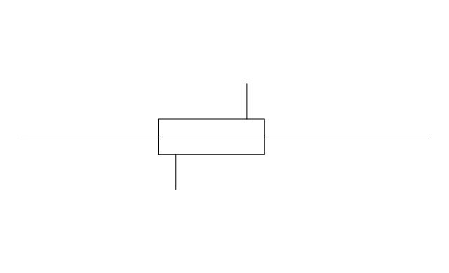
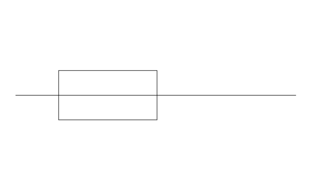
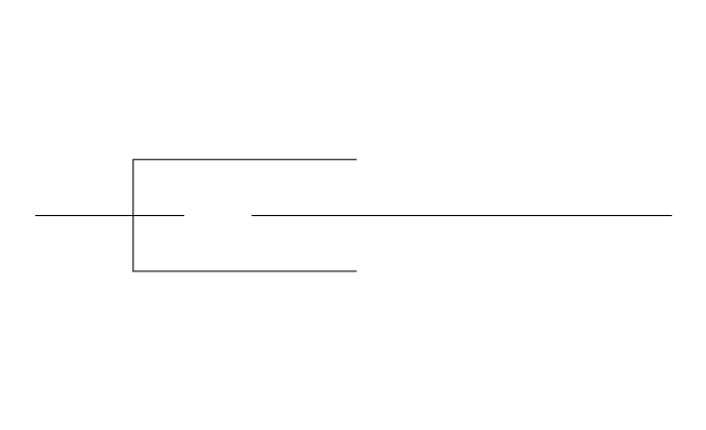
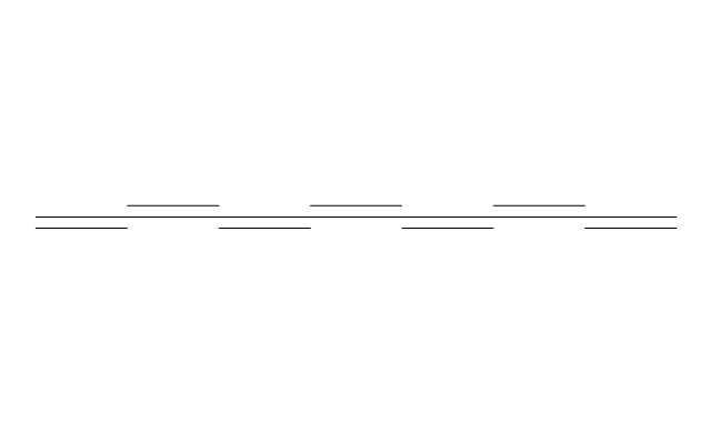
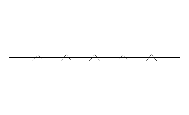
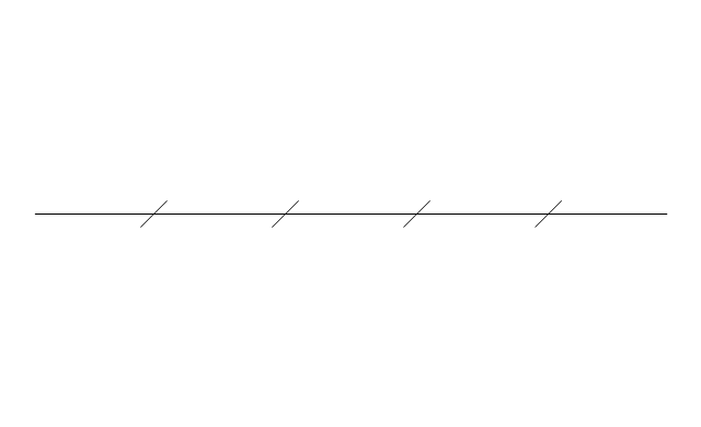
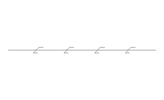
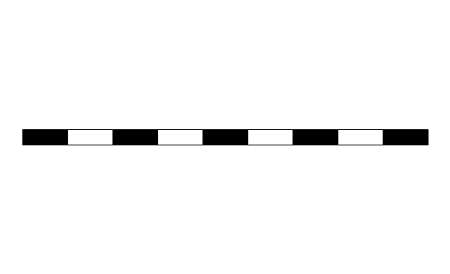
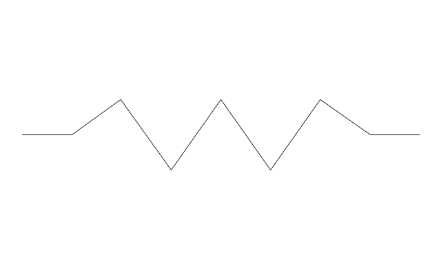
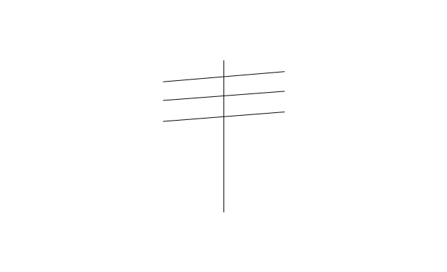
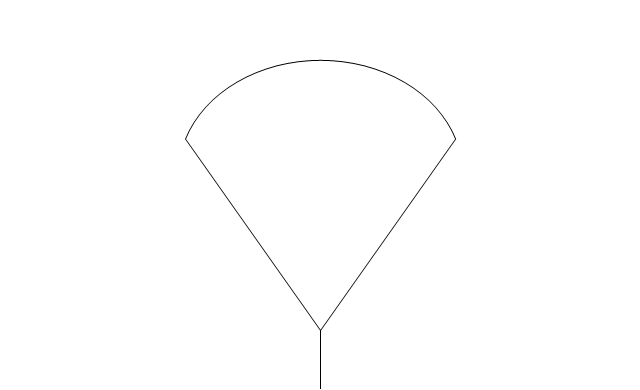
The vector stencils library "Pipes 2" contains 48 symbols of pipes. Use it for drawing plumbing and piping building plans, schematic diagrams, blueprints, or technical drawings of waste water disposal systems, hot and cold water supply systems in the ConceptDraw PRO diagramming and vector drawing software extended with the Plumbing and Piping Plans solution from the Building Plans area of ConceptDraw Solution Park.
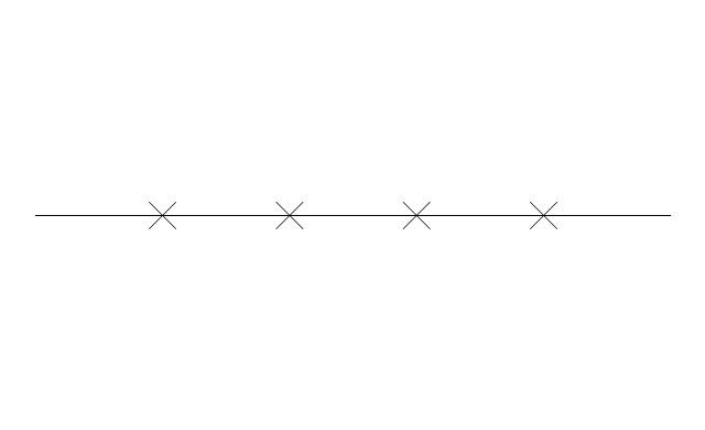
Crossing
Junction
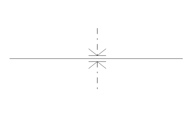
Basic support
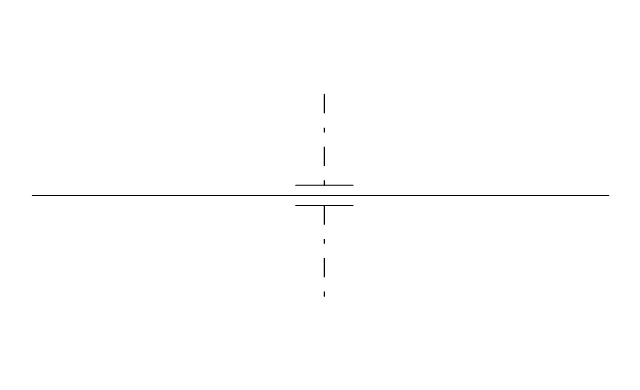
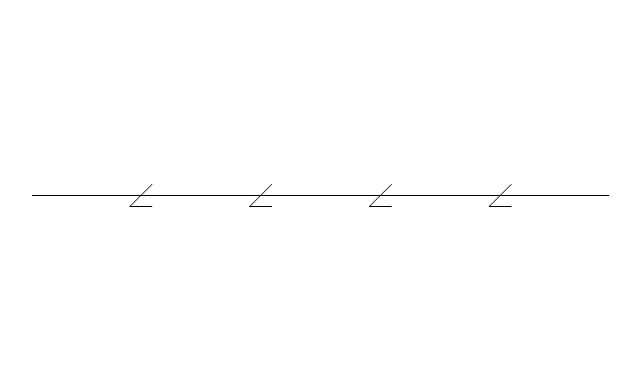
Guide 1
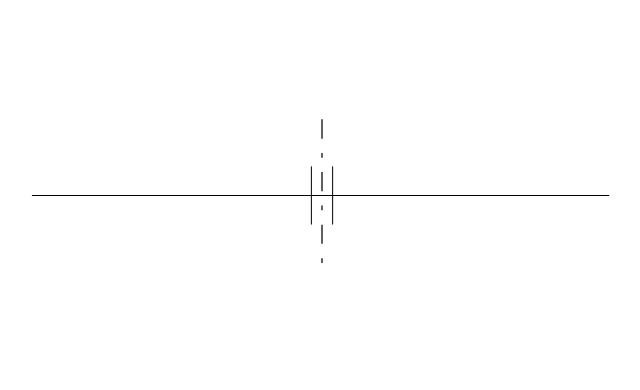
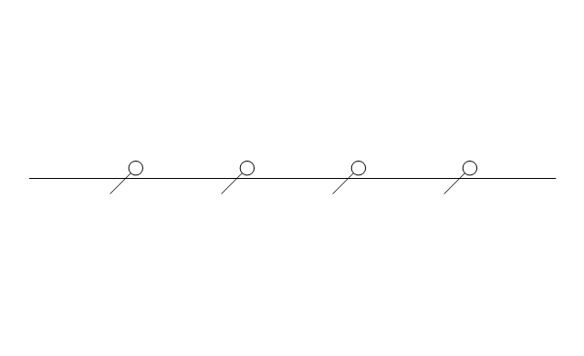
Guide 2
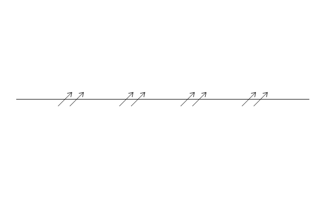
Guide 3
Stopper
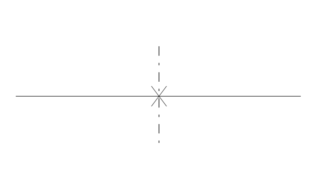
Anchor
Support / anchor
Hunger
Cross
Double branch
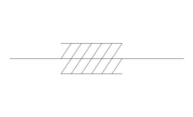
Jacketed
Sleeved
Sleeve joint
Expansion sleeve joint
Lagged
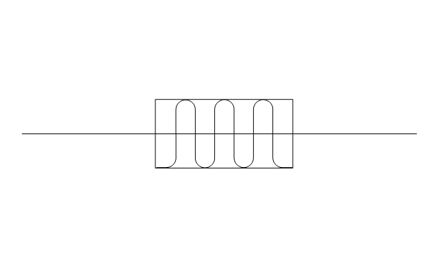
Bellows
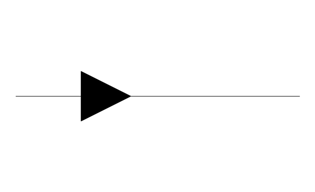
Flow indication
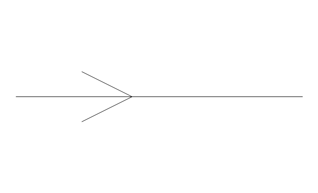
Flow indication 2
Reducer
Reducer,arrow
Pipe bore change
Flexibility provision
Sleeve extension
Flow restrictor
Elbow 45
Elbow 90
Heated or cooled
Pneumatic line
Signal line
Electric line
Hydraulic line
Capillary line
Internal connection
Route radiation
Mechanical linkage
Electrical device
Vibratory device
Weight device
Spray device
Rotary motion
Stirring / fan
Access points
Trap
Expansion loop
Flexible hose
Flexible hose, flanged
Retract resistor check valve application: pneumatic cylinder, piston driven by Compressed air through 2 Retract resistor check valves.
"A check valve, clack valve, non-return valve or one-way valve is a valve that normally allows fluid (liquid or gas) to flow through it in only one direction.
Check valves are two-port valves, meaning they have two openings in the body, one for fluid to enter and the other for fluid to leave. There are various types of check valves used in a wide variety of applications. Check valves are often part of common household items. Although they are available in a wide range of sizes and costs, check valves generally are very small, simple, or inexpensive. Check valves work automatically and most are not controlled by a person or any external control; accordingly, most do not have any valve handle or stem. The bodies (external shells) of most check valves are made of plastic or metal.
An important concept in check valves is the cracking pressure which is the minimum upstream pressure at which the valve will operate. Typically the check valve is designed for and can therefore be specified for a specific cracking pressure.
Heart valves are essentially inlet and outlet check valves for the heart ventricles, since the ventricles act as pumps." [Check valve. Wikipedia]
This hydraulic schematic example was redrawn using ConceptDraw PRO diagramming and vector drawing software from the Wikimedia Commons file: Retract resistor check valve application.png.
[commons.wikimedia.org/ wiki/ File:Retract_ resistor_ check_ valve_ application.png]
The hydraulic engineering drawing example "Retract resistor check valve application" was created using the ConceptDraw PRO diagramming and vector drawing software extended with the Mechanical Engineering solution from the Engineering area of ConceptDraw Solution Park.
Hydraulic schematic

- Hydraulic schematic | Hydraulic circuits | Mechanical Drawing ...
- Hydraulic circuits | Mechanical Drawing Symbols | Technical ...
- Draw A Circuit Diagram Of A Hydraulic Engineering System
- Mechanical Engineering | Technical Drawing Software | Engineering ...
- Mechanical Drawing Symbols | Technical Drawing Software ...
- Basic Schematic Diagram Of Hydraulic Circuit
- How To Draw A Mechanical Engineering Schematics
- Mechanical Engineering | Hydraulic schematic | Technical Drawing ...
- Technical Drawing Software | Mechanical Engineering | Design ...
- Technical Drawing Software | Mechanical Drawing Symbols ...
- Technical Drawing Software | Mechanical Drawing Symbols ...
- Technical Drawing Software | Mechanical Engineering | Mechanical ...
- Mechanical Drawing Symbols | Sketch Layout Of Basic Hydraulic ...
- Basic Hydraulic Circuit Sketch
- Technical Drawing Software | Mechanical Drawing Symbols ...
- Mechanical Drawing Symbols | Mechanical Drawing Software ...
- Circuits and Logic Diagram Software | Hydraulic schematic ...
- Mechanical Drawing Symbols | Technical Drawing Software ...
- Hydraulic Circuit Diagram Wikipedia
- Electrical Symbols , Electrical Diagram Symbols | Circuits and Logic ...