"Network planning and design is an iterative process, encompassing topological design, network-synthesis, and network-realization, and is aimed at ensuring that a new telecommunications network or service meets the needs of the subscriber and operator. Network planning process involves three main steps: 1) Topological design: This stage involves determining where to place the components and how to connect them. 2) Network-synthesis: This stage involves determining the size of the components used, subject to performance criteria such as the Grade of Service (GoS). 3) Network realization: This stage involves determining how to meet capacity requirements, and ensure reliability within the network." [Network planning and design. Wikipedia]
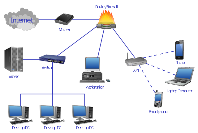
This computer network system design diagram example was created using the ConceptDraw PRO diagramming and vector drawing software extended with the Computer and Networks solution from the Computer and Networks area of ConceptDraw Solution Park.
This computer network system design diagram example was created using the ConceptDraw PRO diagramming and vector drawing software extended with the Computer and Networks solution from the Computer and Networks area of ConceptDraw Solution Park.
Network system design
"General packet radio service (GPRS) is a packet oriented mobile data service on the 2G and 3G cellular communication system's global system for mobile communications (GSM). GPRS was originally standardized by European Telecommunications Standards Institute (ETSI) in response to the earlier CDPD and i-mode packet-switched cellular technologies. It is now maintained by the 3rd Generation Partnership Project (3GPP).
GPRS usage is typically charged based on volume of data transferred, contrasting with circuit switched data, which is usually billed per minute of connection time. Usage above the bundle cap is either charged per megabyte or disallowed.
GPRS is a best-effort service, implying variable throughput and latency that depend on the number of other users sharing the service concurrently, as opposed to circuit switching, where a certain quality of service (QoS) is guaranteed during the connection. In 2G systems, GPRS provides data rates of 56–114 kbit/ second. 2G cellular technology combined with GPRS is sometimes described as 2.5G, that is, a technology between the second (2G) and third (3G) generations of mobile telephony. It provides moderate-speed data transfer, by using unused time division multiple access (TDMA) channels in, for example, the GSM system. GPRS is integrated into GSM Release 97 and newer releases." [General Packet Radio Service. Wikipedia]
This GPRS network diagram example was created using the ConceptDraw PRO diagramming and vector drawing software extended with the Telecommunication Network Diagrams solution from the Computer and Networks area of ConceptDraw Solution Park.
GPRS network diagram

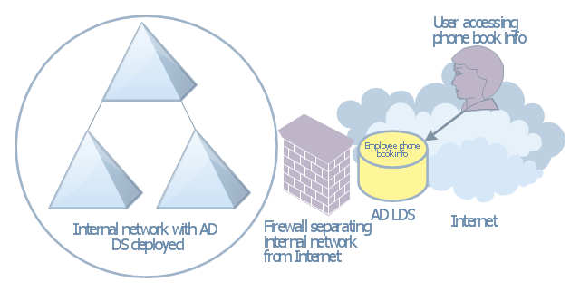
This AD diagram example was created based on the picture "AD LDS as a phone book service" from the book "Active Directory for Dummies".
"Directory services are a great way of providing information that can be fre-
quently retrieved and searched on in a hierarchical way. ... Well, there’s no reason that you can’t create a directory service that’s actually a phone book. Imagine that you need to make a searchable phone directory of your organization available on the Internet. ... This isn’t a difficult task, but it has security repercussions. If you’ve already deployed AD DS and you have the employees’ phone numbers available in that directory, it might not be a good idea to expose your AD DS environment to the Internet for security reasons. Using AD LDS is a great alternative because it can be deployed separately from AD DS and it’s designed to simply provide the information retrieval service that you need without the complications involved with Kerberos authentication and group policies." [Steve Clines and Marcia Loughry, Active Directory® For Dummies®, 2nd Edition. 2008]
The Active Directory diagram example "AD LDS as a phone book service" was created using the ConceptDraw PRO diagramming and vector drawing software extended with the Active Directory Diagrams solution from the Computer and Networks area of ConceptDraw Solution Park.
Active Directory network diagram
This interactive voice response (IVR) diagram sample illustrates how ENUM call forwarding can be achieved. It was designed on the base of the Wikimedia Commons file: Call Forwarding with ENUM.jpg. [commons.wikimedia.org/ wiki/ File:Call_ Forwarding_ with_ ENUM.jpg]
"Telephone number mapping is a system of unifying the international telephone number system of the public switched telephone network with the Internet addressing and identification name spaces. Internationally, telephone numbers are systematically organized by the E.164 standard, while the Internet uses the Domain Name System (DNS) for linking domain names to IP addresses and other resource information. Telephone number mapping systems provide facilities to determine applicable Internet communications servers responsible for servicing a given telephone number using DNS queries.
The most prominent facility for telephone number mapping is the E.164 Number Mapping (ENUM) standard. It uses special DNS record types to translate a telephone number into a Uniform Resource Identifier (URI) or IP address that can be used in Internet communications." [Telephone number mapping. Wikipedia]
The IVR diagram example "Call Forwarding with ENUM" was designed using ConceptDraw PRO diagramming and vector drawing software extended with the Interactive Voice Response Diagrams solution from the Computer and Networks area of ConceptDraw Solution Park.
IVR diagram

Computer network documentation is important part of industry best practices. It used by network engineers, service providers and value-added resellers (VARs) for documenting corporate and customers' networks. Network documentation is very helpful in technical maintenance, troubleshooting, upgrading and IT specialist training processes.
The basic computer network diagram example was created using the ConceptDraw PRO diagramming and vector drawing software extended with the Computer and Networks solution from the Computer and Networks area of ConceptDraw Solution Park.
The basic computer network diagram example was created using the ConceptDraw PRO diagramming and vector drawing software extended with the Computer and Networks solution from the Computer and Networks area of ConceptDraw Solution Park.
Network diagram

The vector stencils library "Cisco products additional" contains 141 symbols of computer network devices and equipment.
"Cisco's products and services focus upon three market segments—Enterprise and Service Provider, Small Business and the Home. ...
Corporate market refers to enterprise networking and service providers.
Borderless networks ... routers, switches, wireless systems, security systems, WAN acceleration, energy and building management systems and media aware networks.
Collaboration ... IP video and phones, TelePresence, HealthPresence, Unified Communications, Call Center systems, Enterprise social networks and Mobile applications.
Datacenter and Virtualization ... Unified Computing, Unified Fabric, Data Centre Switching, Storage Networking and Cloud Computing services.
IP NGN (Next Generation Networks) ... High-end routing and switching for fixed and mobile service provider networks, broadcast video contribution/ distribution, entitlement and content delivery systems. ...
Small businesses include home businesses and (usually technology-based) startups.
Home user refers to individuals or families who require these kinds of services." [Cisco Systems. Wikipedia]
Create the computer network toplogy diagrams using the ConceptDraw PRO diagramming and vector drawing software with the design elements library "Cisco products additional".
The example "Design elements - Cisco products additional" is included in the Cisco Network Diagrams solution from the Computer and Networks area of ConceptDraw Solution Park.
Cisco products additional symbols

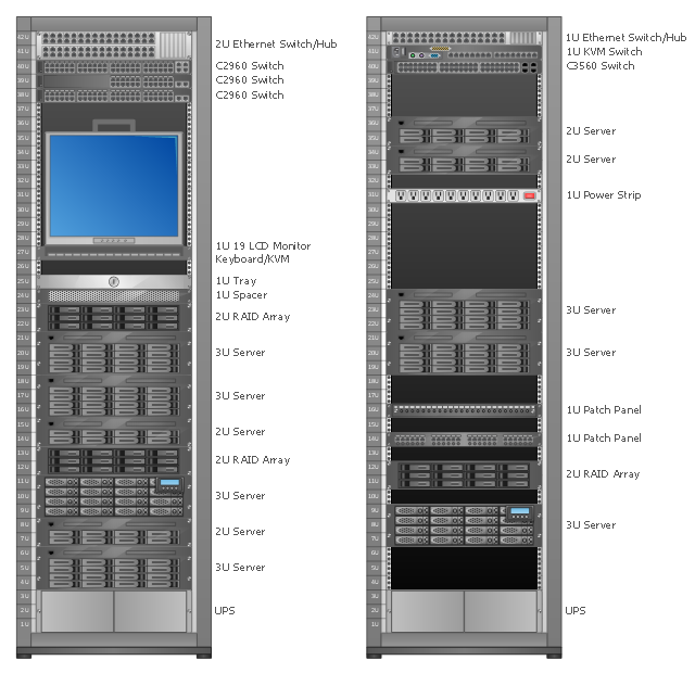
Rack Diagrams visualize the rack mounting of computer hardware and network equipment as the drawing of frontal view of the rack with equipment installed.
They are used for choosing the equipment or racks to buy, and help to organize equipment on the racks virtually, without the real installation.
"A server is a system (software and suitable computer hardware) that responds to requests across a computer network to provide, or help to provide, a network service. Servers can be run on a dedicated computer, which is also often referred to as "the server", but many networked computers are capable of hosting servers. In many cases, a computer can provide several services and have several servers running. ...
Servers often provide essential services across a network, either to private users inside a large organization or to public users via the Internet. Typical computing servers are database server, file server, mail server, print server, web server, gaming server, application server..." [Server (computing). Wikipedia]
This network server rack diagram example was created using the ConceptDraw PRO diagramming and vector drawing software extended with the Rack Diagrams solution from the Computer and Networks area of ConceptDraw Solution Park.
Rack diagram
The vector stencils library "Cisco routers" contains 27 symbols of routers for drawing Cisco computer network diagrams.
"When multiple routers are used in interconnected networks, the routers exchange information about destination addresses using a dynamic routing protocol. Each router builds up a table listing the preferred routes between any two systems on the interconnected networks. A router has interfaces for different physical types of network connections, (such as copper cables, fiber optic, or wireless transmission). It also contains firmware for different networking Communications protocol standards. Each network interface uses this specialized computer software to enable data packets to be forwarded from one protocol transmission system to another.
Routers may also be used to connect two or more logical groups of computer devices known as subnets, each with a different sub-network address. The subnets addresses recorded in the router do not necessarily map directly to the physical interface connections." [Router (computing). Wikipedia]
The symbols example "Cisco routers - Vector stencils library" was created using the ConceptDraw PRO diagramming and vector drawing software extended with the Cisco Network Diagrams solution from the Computer and Networks area of ConceptDraw Solution Park.
www.conceptdraw.com/ solution-park/ computer-networks-cisco
Router

Router, subdued

Router with silicon switch

Wavelength router

NetFlow router

uBR 910

Broadband router

Gigabit switch ATM tag router

ATM tag switch router

ATM router

NetFlow router

Cisco 7505

Cisco 7507

Cisco 7500 ARS (7513)
-cisco-routers---vector-stencils-library.png--diagram-flowchart-example.png)
Voice enabled router

TDM router

IP telephony router

IAD router

Content service router

Cisco storage router

Router with firewall

Wireless router

ASR 1000 series

ATM 3800

AXP

Cable modem

Ground terminal

The vector stencils library "Logical network diagram" contains 16 symbols for drawing logical computer network diagrams.
"The logical topology ... is the way that the signals act on the network media, or the way that the data passes through the network from one device to the next without regard to the physical interconnection of the devices. A network's logical topology is not necessarily the same as its physical topology. ...
The logical classification of network topologies generally follows the same classifications as those in the physical classifications of network topologies but describes the path that the data takes between nodes being used as opposed to the actual physical connections between nodes. The logical topologies are generally determined by network protocols as opposed to being determined by the physical layout of cables, wires, and network devices or by the flow of the electrical signals, although in many cases the paths that the electrical signals take between nodes may closely match the logical flow of data, hence the convention of using the terms logical topology and signal topology interchangeably.
Logical topologies are often closely associated with Media Access Control methods and protocols. Logical topologies are able to be dynamically reconfigured by special types of equipment such as routers and switches." [Network topology. Wikipedia]
The symbols example "Logical network diagram - Vector stencils library" was created using the ConceptDraw PRO diagramming and vector drawing software extended with the Computer and Networks solution from the Computer and Networks area of ConceptDraw Solution Park.
www.conceptdraw.com/ solution-park/ computer-and-networks
Server

Disk

Printer

Domain

Network

File

Group

Root

Shared Admin

Directory

Tree

NDS Container

Unknown

Neightborhood

Service

Information

"In computer networking, cloud computing is computing that involves a large number of computers connected through a communication network such as the Internet, similar to utility computing. ...
Network-based services, which appear to be provided by real server hardware, and are in fact served up by virtual hardware, simulated by software running on one or more real machines are often called cloud computing. Such virtual servers do not physically exist and can therefore be moved around and scaled up or down on the fly without affecting the end user, somewhat like a cloud becoming larger or smaller without being a physical object. ...
Typically, the seller has actual energy-consuming servers which host products and services from a remote location, so end-users don't have to; they can simply log on to the network without installing anything. The major models of cloud computing service are known as software as a service, platform as a service, and infrastructure as a service. These cloud services may be offered in a public, private or hybrid network. Google, Amazon,leadsquared.com, Oracle Cloud, Salesforce, Zoho, Access2MyPC, and Microsoft Azure are some well-known cloud vendors." [Cloud computing. Wikipedia]
The AWS architecture diagram example "2-Tier Auto-scalable Web Application Architecture in 1 AZ" was created using the ConceptDraw PRO diagramming and vector drawing software extended with the AWS Architecture Diagrams solution from the Computer and Networks area of ConceptDraw Solution Park.
AWS architecture diagram
.png--diagram-flowchart-example.png)
- Computer network system design diagram | Diagramming software ...
- How to Draw a Computer Network Diagrams | Computer network ...
- Network Diagram Software Home Area Network | Diagramming
- Diagramming software for Amazon Web Service icon set ...
- Diagramming software for Amazon Web Service diagrams, charts ...
- Hotel Service Process | Mini Hotel Floor Plan. Floor Plan Examples ...
- How To create Diagrams for Amazon Web Services architecture ...
- AWS Architecture Diagrams | Software Development | Diagramming ...
- Computer network system design diagram | How to Draw a ...
- Diagramming software for Amazon Web Service diagrams, charts ...
- AWS Simple Icons for Architecture Diagrams | Diagramming ...
- Diagramming software for Amazon Web Service diagrams, charts ...
- How to Draw a Computer Network Diagrams | Diagramming tool ...
- How to Draw a Computer Network Diagrams | Computer network ...
- Computer network diagram
- Network wiring cable. Computer and Network Examples | Network ...
- Network Gateway Router | Cisco Intelligent Services Gateway | How ...
- Diagramming software for Amazon Web Service diagrams, charts ...
- How to Draw a Computer Network Diagrams | Business Diagram ...
- How to Draw a Computer Network Diagrams | Mobile satellite ...