Diagramming Software for Design UML Communication Diagrams


Communication Diagram UML2.0 / Collaboration UML1.x

Diagramming Software for Design UML Collaboration Diagrams

UML Collaboration Diagram Example Illustration

UML Deployment Diagram Example - ATM System UML diagrams

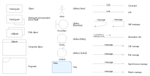
The vector stencils library "UML communication diagrams" contains 23 symbols for the ConceptDraw PRO diagramming and vector drawing software.
"... communication diagrams use the free-form arrangement of objects and links as used in Object diagrams. In order to maintain the ordering of messages in such a free-form diagram, messages are labeled with a chronological number and placed near the link the message is sent over. Reading a communication diagram involves starting at message 1.0, and following the messages from object to object." [Communication diagram. Wikipedia]
The example "Design elements - UML communication diagrams" is included in the Rapid UML solution from the Software Development area of ConceptDraw Solution Park.
UML communication diagram symbols
Digital Communications Network. Computer and Network Examples


 Computers and Communications
Computers and communications solution extends ConceptDraw PRO software with illustration samples, templates and vector stencils libraries with clip art of computers, control devices, communications, technology, Apple machines.
Network Drawing Software

UML Use Case Diagram Example Registration System

UML Diagram Types List

"The client–server model of computing is a distributed application structure that partitions tasks or workloads between the providers of a resource or service, called servers, and service requesters, called clients. Often clients and servers communicate over a computer network on separate hardware, but both client and server may reside in the same system. A server host runs one or more server programs which share their resources with clients. A client does not share any of its resources, but requests a server's content or service function. Clients therefore initiate communication sessions with servers which await incoming requests.
Examples of computer applications that use the client–server model are Email, network printing, and the World Wide Web." [Client–server model. Wikipedia]
The UML communication diagram example "Client server access" was created using the ConceptDraw PRO diagramming and vector drawing software extended with the Rapid UML solution from the Software Development area of ConceptDraw Solution Park.
UML communication diagram

UML Use Case Diagram Example - Estate Agency

Near field communication (NFC). Computer and Network Examples
. Computer and Network Examples")
UML Collaboration Diagram. Design Elements

- Communication Diagram Examples
- Diagramming Software for Design UML Collaboration Diagrams ...
- Diagramming Software for Design UML Communication Diagrams ...
- UML Collaboration Diagram Example Illustration | Diagramming ...
- Diagramming Software for Design UML Communication Diagrams ...
- UML Tool & UML Diagram Examples | Communication Diagram ...
- Tv Communication Diagram
- Network Communication Diagram
- Communication Diagram Example For Online Shopping
- UML Tool & UML Diagram Examples | Communication Diagram ...
- Diagramming Software for Design UML Communication Diagrams ...
- Design elements - Bank UML communication diagram | Design ...
- What Is Point To Multipoint Communication With Diagram
- Diagramming Software for Design UML Communication Diagrams ...
- Automated payroll management system UML activity diagram | UML ...
- Communication Diagram UML2.0 / Collaboration UML1.x ...
- Example Of Diagram In Communication Elements
- UML communication diagram - Client server access | Diagramming ...
- UML communication diagram - Template | Diagramming Software ...
- Idea Outline | UML communication diagram - Client server access ...