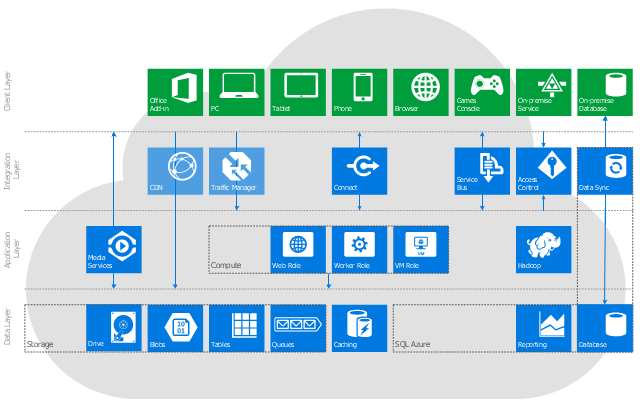
This cloud computing system architecture diagram example was created on the base of the picture in the post "Windows Azure Solution Cookbook" from the Clint Edmonson's blog notsotrivial.net.
"The diagram you see ... is designed to provide a layered architectural overview of the developer and infrastructure services currently available in Windows Azure." [notsotrivial.net/ blog/ post/ 2012/ 07/ 02/ Windows-Azure-Solution-Cookbook.aspx]
The diagram example "Microsoft Azure reference architecture" was created using ConceptDraw PRO diagramming and vector drawing software extended with the Azure Architecture solution from the Computer and Networks area of ConceptDraw Solution Park.
Cloud computing system architecture diagram
 ConceptDraw Solution Park
ConceptDraw Solution Park collects graphic extensions, examples and learning materials
 Computer Network Diagrams
Computer Network Diagrams solution extends ConceptDraw PRO software with samples, templates and libraries of vector icons and objects of computer network devices and network components to help you create professional-looking Computer Network Diagrams, to plan simple home networks and complex computer network configurations for large buildings, to represent their schemes in a comprehensible graphical view, to document computer networks configurations, to depict the interactions between network's components, the used protocols and topologies, to represent physical and logical network structures, to compare visually different topologies and to depict their combinations, to represent in details the network structure with help of schemes, to study and analyze the network configurations, to communicate effectively to engineers, stakeholders and end-users, to track network working and troubleshoot, if necessary.
 AWS Architecture Diagrams
AWS Architecture Diagrams with powerful drawing tools and numerous predesigned Amazon icons and AWS simple icons is the best for creation the AWS Architecture Diagrams, describing the use of Amazon Web Services or Amazon Cloud Services, their application for development and implementation the systems running on the AWS infrastructure. The multifarious samples give you the good understanding of AWS platform, its structure, services, resources and features, wide opportunities, advantages and benefits from their use; solution’s templates are essential and helpful when designing, description and implementing the AWS infrastructure based systems. Use them in technical documentation, advertising and marketing materials, in specifications, presentation slides, whitepapers, datasheets, posters, etc.
 Entity-Relationship Diagram (ERD)
An Entity-Relationship Diagram (ERD) is a visual presentation of entities and relationships. That type of diagrams is often used in the semi-structured or unstructured data in databases and information systems. At first glance ERD is similar to a flowch
- Introduction to Cloud Computing Architecture | SharePoint server ...
- SharePoint server reference architecture for public-facing website ...
- Microsoft Azure reference architecture | ConceptDraw Solution Park ...
- Enterprise Architecture Diagrams | Amazon Cloud Computing ...
- AWS Architecture Diagrams | Diagramming tool - Amazon Web ...
- Cloud Computing Blog
- Microsoft Azure | Azure Architecture | Microsoft Azure reference ...
- SharePoint server reference architecture for public-facing website ...
- Introduction to Cloud Computing Architecture | SharePoint server ...
- Cloud Computing Diagrams | ER Diagram for Cloud Computing ...
- Cloud Services Overview
- Cloud Computing Diagrams | Cloud Computing Architecture ...
- Cloud Computing Diagrams
- Cloud Computing Vendors
- How to Create a Cloud Computing Diagram Using ConceptDraw ...
- Example Of Cloud Computing
- Windows Azure | Sequence Diagram for Cloud Computing | Amazon ...
- Cloud Computing Architecture Diagrams | Architecture Diagrams ...
- Cloud Computing Architecture | How to Install ConceptDraw on a ...
- Virtual Cloud Computing