This circular arrows diagram sample shows business process management life cycle.
It was designed on the base of the Wikimedia Commons file: Business Process Management Life-Cycle.svg. [commons.wikimedia.org/ wiki/ File:Business_ Process_ Management_ Life-Cycle.svg]
This file is licensed under the Creative Commons Attribution-Share Alike 3.0 Unported license. [creativecommons.org/ licenses/ by-sa/ 3.0/ deed.en]
"BPM life-cycle.
Business process management activities can be grouped into six categories: vision, design, modeling, execution, monitoring, and optimization.
Functions are designed around the strategic vision and goals of an organization. Each function is attached with a list of processes. Each functional head in an organization is responsible for certain sets of processes made up of tasks which are to be executed and reported as planned. Multiple processes are aggregated to function accomplishments and multiple functions are aggregated to achieve organizational goals." [Business process management. Wikipedia]
The arrow donut chart example "BPM life cycle" was created using the ConceptDraw PRO diagramming and vector drawing software extended with the Circular Arrows Diagrams solution from the area "What is a Diagram" of ConceptDraw Solution Park.
Circular arrows diagram

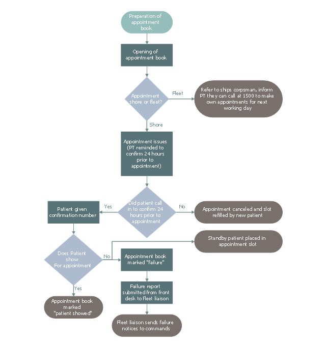
This business process flowchart example was redesigned from the Wikimedia Commons file: Proposed Patient Appointment Procedure.png.
[commons.wikimedia.org/ wiki/ File:Proposed_ Patient_ Appointment_ Procedure.png]
"The example is Proposed Patient Appointment Procedure. It starts with "preparation of appointment book" followed by a decision whether the appointment is shore or fleet. If the appointment is fleet, inform patient they can call 1500 to make own appointments for next few days, if the appointment is shore, confirm 24 hours prior to appointment. Next confirm that the patient confirmed. If a patient did not call, the appointment is canceled, otherwise the patient is given a confirmation number. Finally confirm that the patient showed for the appointment. If not, a standby patient is placed in the appointment slot, the appointment book is marked “Failure” and a failure report is submitted from front desk to fleet liaison. If a patient showed for appointment, put “Patient showed” in appointment book." [Business process mapping. Wikipedia]
The business process map "Proposed Patient Appointment Procedure" was drawn using the ConceptDraw PRO diagramming and business graphics software extended with the Business Process Mapping solution from the Business Processes area of ConceptDraw Solution Park.
Business process map
 Event-driven Process Chain Diagrams
Event-driven Process Chain (EPC) Diagram is a type of flowchart widely used for modeling in business engineering and reengineering, business process improvement, and analysis. EPC method was developed within the Architecture of Integrated Information Systems (ARIS) framework.
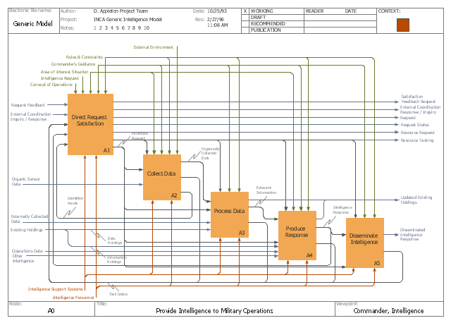
This IDEF0 diagram example was redesigned from the Wikimedia Commons file: C4ISR Architecture Framework, Example Activity Diagram in IDEF0 Format.jpg. [commons.wikimedia.org/ wiki/ File:C4ISR_ Architecture_ Framework,_ Example_ Activity_ Diagram_ in_ IDEF0_ Format.jpg]
"... the C4ISR concept of Command, Control, Communications, Computers, Intelligence, Surveillance and Reconnaissance ..." [en.wikipedia.org/ wiki/ C4ISR]
"The C4ISR Architectural Framework (C4ISR AF) is now known as DoDAF, is a reference model developed by the US Department of Defense in the 1990s." [commons.wikimedia.org/ wiki/ Category:C4ISR_ Architecture_ Framework]
"The Department of Defense Architecture Framework (DoDAF) is an architecture framework for the United States Department of Defense (DoD) that provides visualization infrastructure for specific stakeholders concerns through viewpoints organized by various views. These views are artifacts for visualizing, understanding, and assimilating the broad scope and complexities of an architecture description through tabular, structural, behavioral, ontological, pictorial, temporal, graphical, probabilistic, or alternative conceptual means.
This Architecture Framework is especially suited to large systems with complex integration and interoperability challenges, and it is apparently unique in its employment of "operational views". These views offer overview and details aimed to specific stakeholders within their domain and in interaction with other domains in which the system will operate." [en.wikipedia.org/ wiki/ Department_ of_ Defense_ Architecture_ Framework]
The example "C4ISR architecture framework - IDEF0 activity diagram" was created using the ConceptDraw PRO diagramming and vector drawing software extended with the solution "IDEF Business Process Diagrams" from the area "Business Processes" of ConceptDraw Solution Park.
IDEF0 business process diagram
Used Solutions
- Wiki Business Process Management
- Business Process Mapping Wiki
- UML Diagram | Design Elements for UML Diagrams | UML Business ...
- Business Process Wikipedia
- Business Process Improvement Wiki
- Wiki Business Process
- BPM life cycle | Pyramid Diagram | Bpm Software Wiki
- Gap Model Wiki
- Business Cycle Wikipedia
- BPMN 2.0 | BPMN | Order process - BPMN 2.0 diagram | Wikipedia ...
- Cross Functional Flowchart Wikipedia
- Selling Process Wikipedia
- BPM Software | Process Mapping | Pyramid Diagram | Bpm Tools ...
- Talent management process | Talent Management Wiki
- Swim Lane Flowchart Symbols | Cross-Functional Flowchart (Swim ...
- Work Order Process Flowchart. Business Process Mapping Examples
- Workflow Management Wiki
- Cross Functional Diagram Wikipedia
- Order processing - Cross-functional flowchart | Order processing ...