HelpDesk
How to Create a Mechanical Diagram
Mechanical Engineering drawing is a type of technical drawing that helps analyze complex engineering systems. Mechanical Engineering diagrams are often a set of detailed drawings used for engineering or construction projects. Making Mechanical Engineering diagram involves many different elements that can be managed using ConceptDraw PRO. You can design elements for drawing parts, assembly, pneumatic, and hydraulic systems for mechanical engineering. With ConceptDraw PRO you can easily create and communicate the Mechanical Engineering diagram of any complexity.HelpDesk
How to Draw a Chemical Process Flow Diagram
Process Flow Diagram widely used in modeling of processes in the chemical industry. A Chemical Process Flow diagram (PFD) is a specialized type of flowchart. With the help of Chemical Process Flow Diagram engineers can easily specify the general scheme of the processes and chemical plant equipment. Chemical Process Flow Diagram displays the real scheme of the chemical process, the relationship between the equipment and the technical characteristics of the process. Chemical Process Flow Diagram illustrates the connections between the basic equipment as well as the overall structure of pipelines and other supporting equipment. The purpose of the PFD is to build the image of the basic idea of the chemical process. ConceptDraw PRO together with its Chemical and Process Engineering solution delivers the possibility to design Chemical Process Flow diagrams. It is designed for chemical industry engineers and designers.HelpDesk
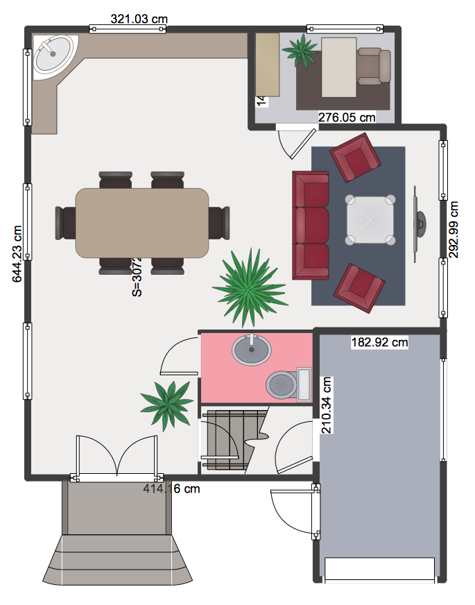
How to Create a Floor Plan Using ConceptDraw PRO
Making a floor plan is the best way to get a handle on how to organize your living space, and find out what could be changed. Creating a floor plan to scale is a challenge of the home and interior design process and can be noticeably helpful for visualizing things like furniture layout. You can use ConceptDraw PRO to produce layouts of real estate properties. ConceptDraw PRO contains the large quantity of pre-designed vector objects that you can use for quick and easy designing such floor plans. You can easily determine the size of the rooms and distances in you drawing. The ability to create a floor plan is delivered by the Floor Plans solution. This solution extends ConceptDraw PRO with libraries that contains over 500 objects of floor plan elements. There is a set of special objects that displays the sizes, corners, squares and other technical details using the current measurements of units.- Technical Drawing Software | Building Drawing Design Element Site ...
- Diagram Of A Layout Of Engineering Drawing Office
- Mechanical Drawing Symbols | Process Flow Diagram Symbols ...
- Shafts And Hoe Diagrams In Engineering Drawing
- How To use House Electrical Plan Software | Technical Drawing ...
- Civil Engineering Drawing Daigarm Com
- Building Engineering Symbols
- Sample Of Building Mechanical Drawing
- Process Flow Diagram Symbols | Technical Drawing Software ...
- Mechanical Drawing Software | Mechanical Drawing Symbols ...
- Mechanical Drawing Symbols | Building Drawing Software for ...
- Piping and Instrumentation Diagram Software | Building Drawing ...
- Mechanical Engineering | How to Create a Mechanical Diagram ...
- Conventional Signs And Symbols Of Engineering Drawings And
- Engineering Drawing Machines Diagrams
- Technical Drawing Software | Mechanical Drawing Symbols ...
- Design elements - Building core | Engineering Drawing Symbol Of ...
- Process flow diagram (PFD) template
- Technical drawing - Machine parts assembling | Mechanical ...


