The vector stencils library "Cisco telepresence" contains 8 symbols of videoconference and telepresence equipment for drawing Cisco computer network diagrams.
"Videoconferencing is the conduct of a videoconference (also known as a video conference or videoteleconference) by a set of telecommunication technologies which allow two or more locations to communicate by simultaneous two-way video and audio transmissions. It has also been called 'visual collaboration' and is a type of groupware. ...
The core technology used in a videoconferencing system is digital compression of audio and video streams in real time. The hardware or software that performs compression is called a codec (coder/ decoder). Compression rates of up to 1:500 can be achieved. The resulting digital stream of 1s and 0s is subdivided into labeled packets, which are then transmitted through a digital network of some kind (usually ISDN or IP). The use of audio modems in the transmission line allow for the use of POTS, or the Plain Old Telephone System, in some low-speed applications, such as videotelephony, because they convert the digital pulses to/ from analog waves in the audio spectrum range.
The other components required for a videoconferencing system include:
(1) Video input : video camera or webcam.
(2) Video output: computer monitor, television or projector.
(3) Audio input: microphones, CD/ DVD player, cassette player, or any other source of PreAmp audio outlet.
(4) Audio output: usually loudspeakers associated with the display device or telephone.
(5) Data transfer: analog or digital telephone network, LAN or Internet.
(6) Computer: a data processing unit that ties together the other components, does the compressing and decompressing, and initiates and maintains the data linkage via the network." [Videoconferencing. Wikipedia]
The symbols example "Cisco telepresence - Vector stencils library" was created using the ConceptDraw PRO diagramming and vector drawing software extended with the Cisco Network Diagrams solution from the Computer and Networks area of ConceptDraw Solution Park.
www.conceptdraw.com/ solution-park/ computer-networks-cisco
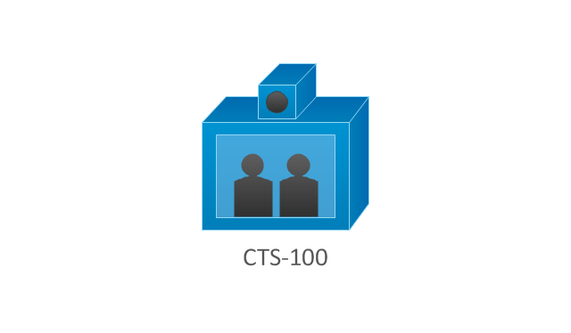
CTS-100
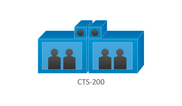
CTS-200
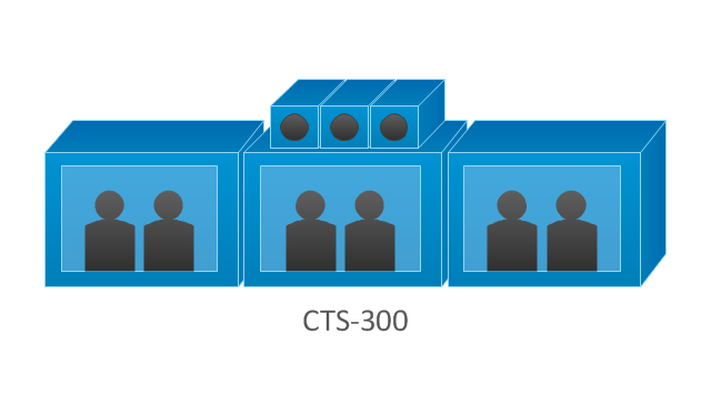
CTS-300
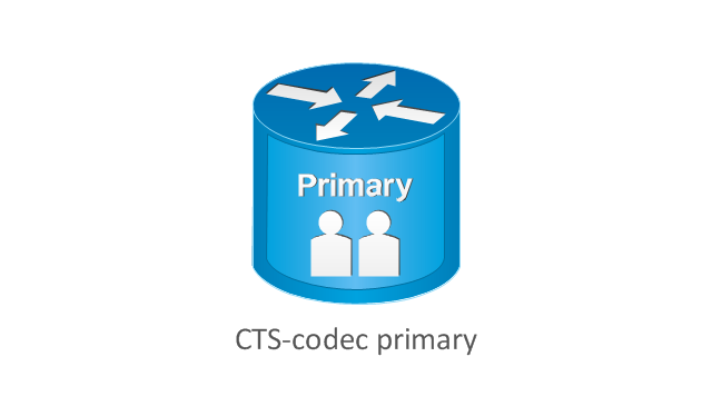
CTS-codec primary
CTS-codec secondary
TP MCU
Cisco telepresence manager
MCU
 Entity-Relationship Diagram (ERD)
An Entity-Relationship Diagram (ERD) is a visual presentation of entities and relationships. That type of diagrams is often used in the semi-structured or unstructured data in databases and information systems. At first glance ERD is similar to a flowch
 eLearning for Skype
This solution extends ConceptDraw MINDMAP software with the ability to prepare and run remote learning sessions by using Skype
 IDEF Business Process Diagrams
Use the IDEF Business Process Diagrams solution to create effective database designs and object-oriented designs, following the integration definition methodology.
"Banks offer many different channels to access their banking and other services:
(1) Automated Teller Machines.
(2) A branch is a retail location.
(3) Call center.
(4) Mail: most banks accept cheque deposits via mail and use mail to communicate to their customers, e.g. by sending out statements.
(5) Mobile banking is a method of using one's mobile phone to conduct banking transactions.
(6) Online banking is a term used for performing multiple transactions, payments etc. over the Internet.
(7) Relationship Managers, mostly for private banking or business banking, often visiting customers at their homes or businesses.
(8) Telephone banking is a service which allows its customers to conduct transactions over the telephone with automated attendant or when requested with telephone operator.
(9) Video banking is a term used for performing banking transactions or professional banking consultations via a remote video and audio connection. Video banking can be performed via purpose built banking transaction machines (similar to an Automated teller machine), or via a video conference enabled bank branch clarification.
(10) DSA is a Direct Selling Agent, who works for the bank based on a contract. Its main job is to increase the customer base for the bank." [Bank. Wikipedia]
The UML use case diagram example "Banking system" was created using the ConceptDraw PRO diagramming and vector drawing software extended with the Rapid UML solution from the Software Development area of ConceptDraw Solution Park.
UML use case diagram

 Spatial Infographics
Spatial infographics solution extends ConceptDraw DIAGRAM software with infographic samples, map templates and vector stencils libraries with design elements for drawing spatial information graphics.
Star Network Topology


 Basic Pie Charts
This solution extends the capabilities of ConceptDraw DIAGRAM (or later) with templates, samples, and a library of vector stencils for drawing pie and donut charts.
 Business Process Model and Notation
Business Process Model and Notation Solution for ConceptDraw DIAGRAM is helpful for modeling the business processes of any degree of complexity, documenting them and effective creating diagrams using the BPMN 2.0 standard.
 Basic Floor Plans
Detailed floor plan is the basis of any building project, whether a home, office, business center, restaurant, shop store, or any other building or premise. Basic Floor Plans solution is a perfect tool to visualize your creative projects, architectural and floor plans ideas.
- Audio Conference Wikipedia
- Design elements - Cisco telepresence | Cisco telepresence - Vector ...
- Cisco telepresence - Vector stencils library | Cisco - Vector stencils ...
- Telecom equipment - Vector stencils library | How To use House ...
- Design elements - Electrical and telecom | Telecommunication ...
- Cisco Network Design. Cisco icons, shapes, stencils, symbols and ...
- Audio - Vector stencils library | Video and TV - Vector stencils library ...
- Audio - Vector stencils library | Video and audio - Vector stencils ...
- Cisco telepresence - Vector stencils library | Mcu Unit Clipart