Unified Modeling Language Diagram
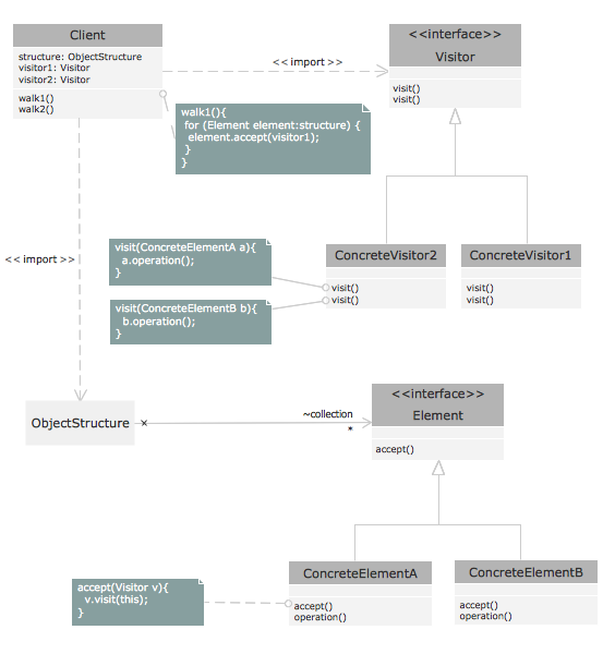
Unified Modeling Language (UML) is an open standard that uses graphic notations for creating visual models of object-oriented software systems.
UML is a language of graphic description for object modeling in the field of software engineering. It was created for definition, visualization, designing of software systems.
There are 13 types of UML diagrams. Rapid UML Solution from the Software Development area of ConceptDraw Solution Park provides templates, samples and libraries with vector objects to help you create the UML diagram of any type quick, easy and effective.
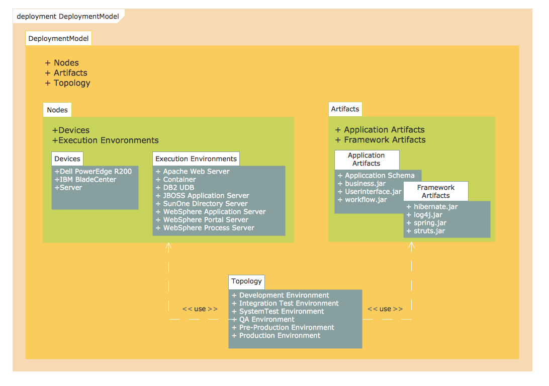
Pic. 1. Unified Modeling Language Diagram - Deployment Model Structure.
This sample was created in ConceptDraw DIAGRAM diagramming and vector drawing software using the UML Package Diagram library of the Rapid UML Solution. It shows the UML Package Diagram that contains nodes and artifacts.
The UML diagrams produced with ConceptDraw DIAGRAM are vector graphic documents and are available for reviewing, modifying, and converting to a variety of formats (image, HTML, PDF file, MS PowerPoint Presentation, Adobe Flash or MS Visio).