Software to Draw Block Diagrams
Block Diagram is a simplified explanation of a system using the blocks to represent the logical and physical components. From here derives its name. It depicts how the block components are related to one another, what type of data, signals, materials flow between the elements, and in what direction. In other words, the blocks describe a system as a collection of parts, each of these parts plays a particular role in a specific context. Different types of relationships can exist between the blocks: association, aggregation, composition, or generalization.
A graphical representation of a system in a form of a Block Diagram is indispensable for understanding its functions. It also helps to create interconnections within it. Block Diagrams are widely used to describe hardware and software systems, engineering systems, electronics, and many different processes in a lot of industries.
ConceptDraw DIAGRAM extended with Block Diagrams solution is a powerful software to draw Block Diagrams. Being supplied with a large set of pre-made vector shapes and connectors, it allows users to design effortlessly even the most complex Block Diagrams. A lot of professionally designed samples and templates are also helpful for all ConceptDraw's users.
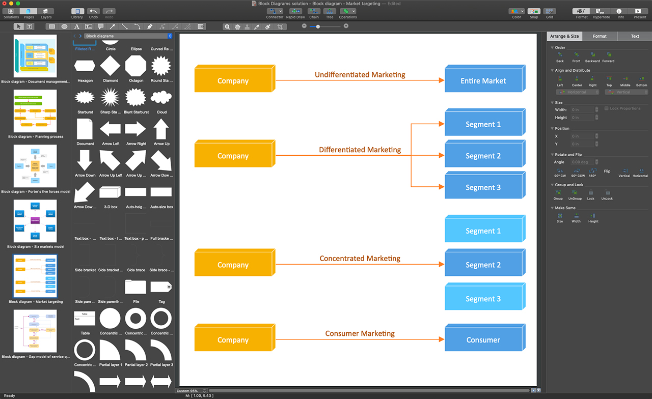
Example 1. ConceptDraw DIAGRAM - Software to Draw Block Diagrams
Get started drawing your Block Diagrams by taking advantage of ConceptDraw DIAGRAM and Block Diagrams solution. Due to the intuitive drag and drop interface, ConceptDraw DIAGRAM is easy-to-use software. You can simply drag desired elements from the libraries to your document. Five libraries of the Block Diagrams solution are at your disposal. Arrange your objects in the desired way and connect with a Smart Connector tool. Simply drag the connector from one connect dot to another making a precise diagram. Add text to the diagram's objects. When your Block Diagram is ready, define your style and apply the corresponding color palette to it. Use the predefined formatting options and styles to format your diagram in minutes.
A large variety of examples and samples included in Block Diagrams solution provides an extensive overview of solution capabilities. Among this variety, there are Six Markets Model , Stages of Promise Issue, Document Management System Architecture, and much more useful examples. Besides, each of these examples can become a good base for your own diagram.

Example 2. Blocks 3D Template
The following features make ConceptDraw DIAGRAM the powerful software to draw Block Diagrams:
- You don't need to be an artist to draw professional-looking diagrams in a few minutes.
- Large quantity of ready-to-use vector objects makes your drawing diagrams quick and simple.
- Great number of predesigned templates and samples give you a good start for your own diagrams.
- ConceptDraw DIAGRAM provides you the possibility to use the grid, rules, and guides. You can easily rotate, group, align, arrange the objects, use different fonts and colors to make your diagram exceptionally looking.
- All ConceptDraw DIAGRAM documents are vector graphic files and are available for reviewing, modifying, and converting to a variety of formats: image, HTML, PDF file, MS PowerPoint Presentation, Adobe Flash, MS Visio.
- Using ConceptDraw STORE you can navigate through ConceptDraw Solution Park, managing downloads and updates. You can access libraries, templates, and samples directly from the ConceptDraw STORE.
- If you have any questions, our free of charge support is always ready to come to your aid.