Made with
ConceptDraw
DIAGRAM 18

Fishbone Diagram

Fishbone Diagram is another name for the Cause and Effect Diagram or the Ishikawa Diagram which got its name from the fact that it looks like a fish skeleton. Developed by Kaoru Ishikawa in 1968, a Fishbone Diagram is effectively used for a cause and effect analysis which allows to consider all possible causes for a certain problem or event.

ConceptDraw DIAGRAM supplied with Fishbone Diagrams solution from the Management area is the best software for fast and easy drawing professional looking Fishbone Diagram.
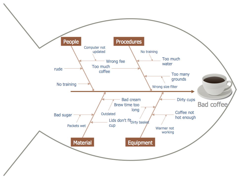
Fishbone Diagram *

Example 1. Fishbone Diagram - Bad Coffee

Fishbone Diagrams Solution offers the Fishbone Diagrams library. 13 ready-to-use objects included in this library allow design the Fishbone diagram of any complexity in minutes.
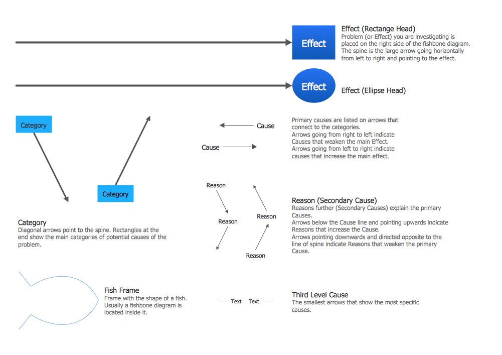
Fishbone Diagrams Library Design Elements

Example 2. Fishbone Diagrams Library Design Elements

Another way of drawing a Fishbone diagram in ConceptDraw DIAGRAM is to use as the base the predesigned template or sample from the ConceptDraw STORE. The whole collection of predesigned templates and samples is offered in it.
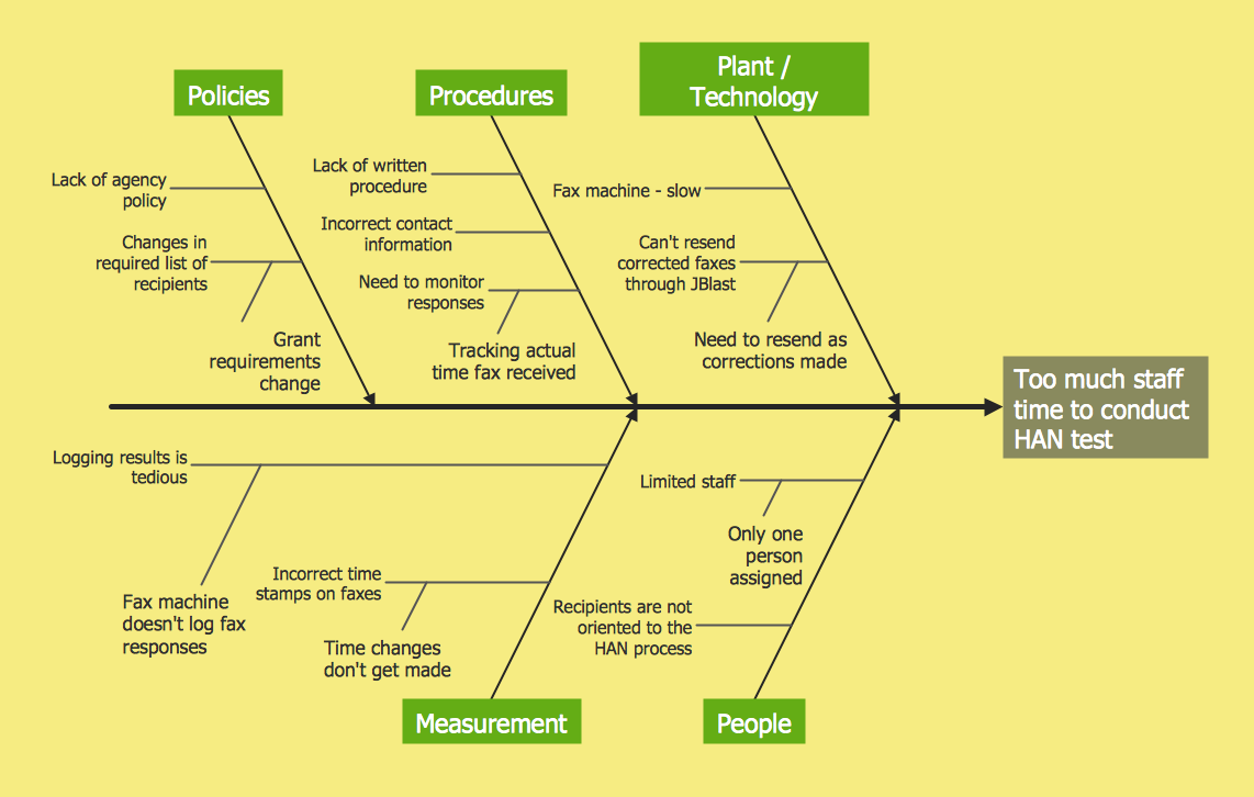
Fishbone Diagram - HAN Project

Example 3. Fishbone Diagram - HAN Project

The Fishbone Diagram samples you see on this page were created in ConceptDraw DIAGRAM using the Fishbone Diagrams Solution. These samples successfully demonstrate solution's capabilities and professional results you can achieve. An experienced user spent 10 minutes creating every of these samples.

Use the Fishbone Diagrams Solution for ConceptDraw DIAGRAM software to create your own professional looking Fishbone Diagram of any complexity quick, easy and effective, and then successfully use it in your work activity.

All source documents are vector graphic documents. They are available for reviewing, modifying, or converting to a variety of formats (PDF file, MS PowerPoint, MS Visio, and many other graphic formats) from the ConceptDraw STORE. The Fishbone Diagrams Solution is available for all ConceptDraw DIAGRAM or later users.
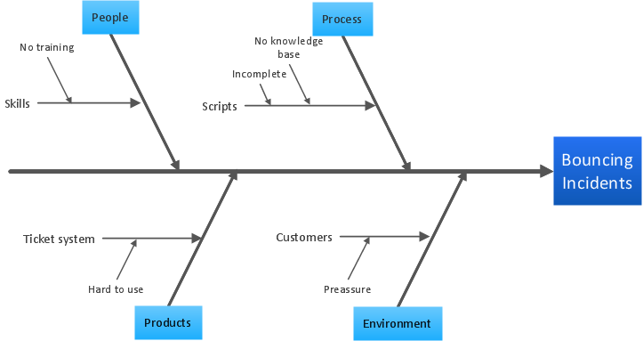




FOUR RELATED HOW TO's:
Fishbone diagram is a powerful tool used for solving business problems and obstacles. ConceptDraw DIAGRAM software extended with Fishbone Diagrams solution from the Management area of ConceptDraw Solution Park is a helpful tool for cause and effect analysis. It gives the ability to easy identify many possible causes and factors which cause the effects and to draw Fishbone Diagrams for problem solving.Cause and Effect Analysis - Fishbone Diagrams for Problem Solving *
Picture: Cause and Effect Analysis - Fishbone Diagrams for Problem Solving
Related Solution:
ConceptDraw DIAGRAM diagramming and vector drawing software enhanced with Fishbone Diagrams solution from the Management area of ConceptDraw Solution Park gives the ability to draw Fishbone diagram, which identifies many possible causes for an effect for problem solving. Fishbone Diagram procedure of creation includes the set of steps easy for execution in ConceptDraw DIAGRAM.Fishbone Diagram Procedure *
Picture: Fishbone Diagram Procedure
Related Solution:
ConceptDraw DIAGRAM diagramming and vector drawing software extended with Flowcharts Solution from the 'Diagrams' area of ConceptDraw Solution Park is a powerful tool for drawing Flow Charts of any complexity you need. Irrespective of whether you want to draw a Simple Flow Chart or large complex Flow Diagram, you estimate to do it without efforts thanks to the extensive drawing tools of Flowcharts solution, there are professional flowchart symbols and basic flowchart symbols. This sample shows the Gravitational Search Algorithm (GSA) that is the optimization algorithm.Simple Flow Chart *
Picture: Simple Flow Chart
Related Solution:
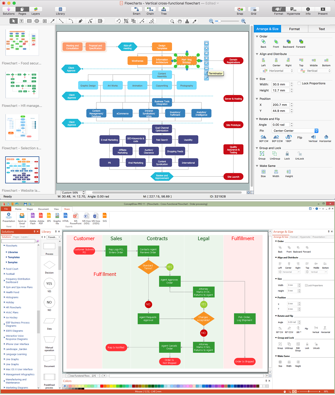
Users can start drawing their own flowchart diagrams in fast and simple way with ConceptDraw software. ConceptDraw DIAGRAM is the only professional diagramming software that works on both Windows and Macintosh platforms. All its documents and libraries are 100% compatible and can be exchanged hassle-free between the platforms.Create a Flow Chart *
Picture: Create a Flow Chart
Related Solution:
ConceptDraw
DIAGRAM 18