Entity Relationship Diagrams
“In software engineering, an entity–relationship model (ER model) is a data model for describing the data or information aspects of a business domain or its process requirements, in an abstract way that lends itself to ultimately being implemented in a database such as a relational database. The main components of ER models are entities (things) and the relationships that can exist among them, and databases.” [from Wikipedia]
The Entity-Relationship Diagram (ERD) Solution from the Software Development Area for ConceptDraw Solution Park extends ConceptDraw DIAGRAM ector graphics and diagramming software with the ability of drawing the Entity Relationship Diagrams for visually describing the databases with Crow’s Foot and Chen's notation icons.
Sample 1. Entity Relationship Diagrams in ConceptDraw DIAGRAM
Drawing the Entity Relationship Diagrams from the clear page can be quite long and hard. For this case, designers were prepared templates and samples with Entity Relationship Diagram examples. Saved and located in ConceptDraw STORE, they are available for every ConceptDraw DIAGRAM user.
 Solution in ConceptDraw STORE")
Sample 2. Entity-Relationship Diagram (ERD) Solution in ConceptDraw STORE
No matter which way you choose - use the predesigned templates and samples, or design Entity Relationship Diagrams de novo, you will be useful to use the vector objects provided by libraries of Entity-Relationship Diagram (ERD) solution.
Sample 3. Entity Relationship Diagrams - ER Model Diagram
This sample was created in ConceptDraw DIAGRAM using the vector objects from the ERD Crow's Foot Notation library of Entity-Relationship Diagram (ERD) Solution and illustrates the Entity Relationship Model Diagram. An experienced user spent 15 minutes creating this sample.
All source documents are vector graphic documents. They are available for reviewing, modifying, or converting to a variety of formats (PDF file, MS PowerPoint, MS Visio, and many other graphic formats) from the ConceptDraw STORE. The Entity-Relationship Diagram (ERD) Solution is available for all ConceptDraw DIAGRAM or later users.
FOUR RELATED HOW TO's:
It is easy to recreate any informational system structure using diagrams. There are three main components of any ER diagram: entity, attribute and relationship. Basing on these three components, one can define other, less used elements, such as weak entity or relationship, derived attribute, recursive relationship etc.
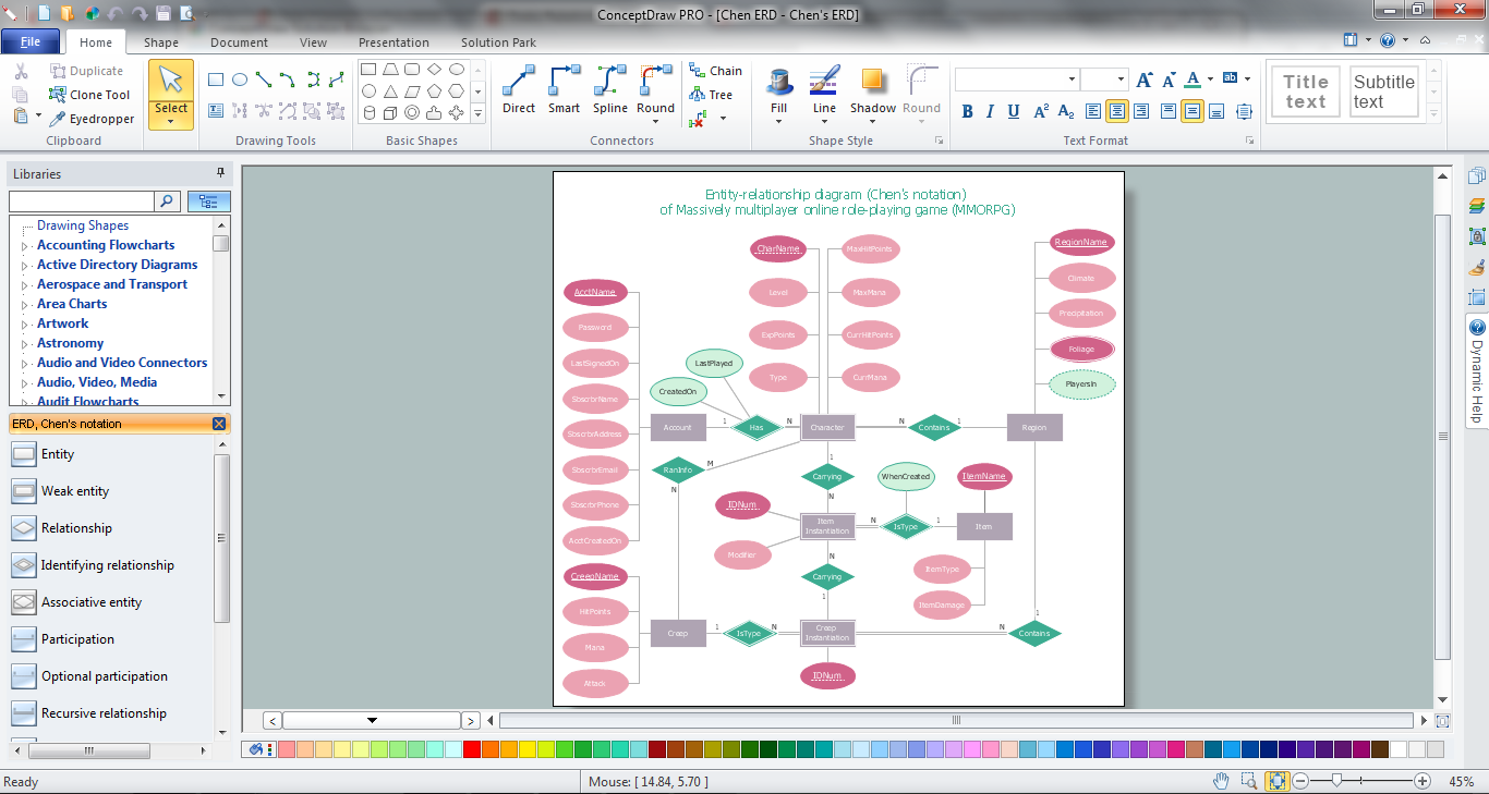
This is the set of graphic elements of ERD Chen's notation. This ERD notation is used to represent an entity–relationship models. It involves the set of geometric forms: rectangles - depicting entities, ovals - representing attributes and diamonds depicting relationships assigned for first-class objects, that can have relationships and attributes of their own. Connections are displayed with arrowed lines. It is known that the Chen's ERD notation is used to show a detailed view of entities and relationships. ConceptDraw Entity-Relationship Diagram solution from the Software Development section of Solution Park provides the ability to create ERD of database structure for software development purposes using the Chen’s notation elements.
Picture: Components of ER Diagram
Related Solution:
Data modelling will help you to study and analyze business processes in your organization for optimization and increase of effectiveness and production.
Picture: Data modeling with ConceptDraw DIAGRAM
While designing a conceptual data model, you should use appropriate software. For instance, ConceptDraw DIAGRAM is a user-friendly ER diagram tool that has a lot of samples and templates to facilitate your work. A clear entity-relationship diagram helps to define the relations between system’s components.
Software engineering is the section of a computer science engaged to design, realization, and support of complex software products. An ERD is a data modeling method that is widely applied in the software engineering practice. Commonly it is used for developing a structure of a a relational database. An entity relationship diagram is helpful for structuring and organizing databases that can be modeled using a relational structure. An entity relationship diagram is designed to depicts the interrelationships within the sets of entities which are accumulated in the database. Each entity represents a particular component of a data. Thus, ER diagrams depicts the logical structure of databases. ConceptDraw ER Diagrams solution provides software engineers with the professional tool for making entity-relationship diagrams.
Picture: Entity Relationship Diagram Software Engineering
Related Solution:
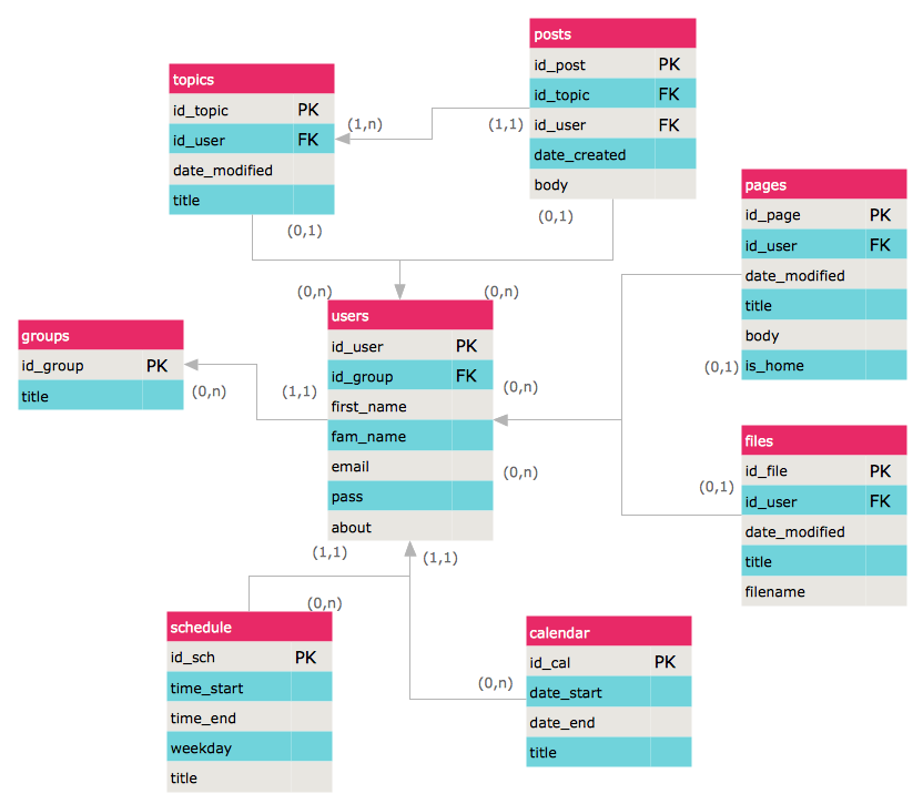
Both Crow’s Foot and Chen’s notations are used to build database models. Each of them has its’ own features, and if you use a proper entity relationship diagram software, you’ll be able to create diagrams of any notation. Database model with clearly defined entities and relationships between them facilitates further work greatly.
This ERD represents the model of Employee Certification Entity. The entity-relationship diagram is a visual instrument of database software development. It is used to structure data and to define the relationships between structured data groups. This ERD was designed with a help of ConceptDraw Entity-Relationship Diagram (ERD) solution. The solution supports the both basic ERD notations used to describe the structure of database: Chen's and Crow’s Foot notations.
Picture: Entity Relationship Software
Related Solution:

 Solution in ConceptDraw STORE")