
Example 1. Android User Interface - Android 5.0 Single Line List
Android User Interface Solution provides the set of 30 libraries with 1088 vector objects which will help you design any desired Android User Interface:
- Android UI
- Android Wallpapers
- Android Product Icons
- Android Lists
- Android Switches and Sliders
- Android Menus
- Android Buttons
- Android Grids
- Android Snackbars and Toasts
- Android Notifications
- Android Bottom Sheets
- Android Chips
- Android Cards
- Android Dialogs
- Android Tabs
- Android Text Fields
- Android System Icons (action, alert)
- Android System Icons (av)
- Android System Icons (communication)
- Android System Icons (content)
- Android System Icons (device)
- Android System Icons (editor)
- Android System Icons (file)
- Android System Icons (hardware)
- Android System Icons (image)
- Android System Icons (maps)
- Android System Icons (navigation)
- Android System Icons (notification)
- Android System Icons (social)
- Android System Icons (toggle)

Example 2. Android UI Library Design Elements
You can start with the objects from the Android UI library or use as the base one of predesigned samples included in Android User Interface Solution. Then use the objects from other libraries of this solution to make your own unique Android User Interface.

Example 3. Android User Interface - Android 5.0 Gmail
The samples you see on this page were created in ConceptDraw DIAGRAM using the objects from the libraries of Android User Interface Solution. Each of these Android User Interfaces successfully demonstrates solution's capabilities and the professional results you can achieve using it. An experienced user spent 10 minutes creating every of them.
Use Android User Interface solution for designing your own Android User Interface fast and easy.
All source documents are vector graphic documents. They are available for reviewing, modifying, or converting to a variety of formats (PDF file, MS PowerPoint, MS Visio, and many other graphic formats) from the ConceptDraw STORE. The Android User Interface Solution is available for all ConceptDraw DIAGRAM or later users.
NINE RELATED HOW TO's:
Data base diagrams describes inter-related data and tables. It describes roles and relationships, internal and external dependencies, data exchange conventions and structures of knowledge domain.
ConceptDraw Software provides number of data-base chart libraries including major 49 vector symbols. Use these DFD flowchart symbol libraries to design data-base structure and models, use it to design data base process-oriented models, or simple data-oriented models. The are special drawing tools for making data flowcharts, data process diagrams, structured analysis diagrams, and information flow diagrams.
Picture: Database Flowchart Symbols
Related Solution:
When thinking about data visualization, one of the first tools that comes to mind is a flowchart design. You can find flowchart symbols, shapes, stencils and icons easily on the Internet, but it might take time to systematize this information. Nevertheless, once you start flowcharting, you’ll love its simplicity and efficiency.
This diagram consists from standard flowchart symbols, approved by ANSI (American National Standard Institute) for drawing flowcharts. A flowchart is a diagram that represents a step-by-step algorithm of any process, displaying the process stages as boxes that are connected with arrows. Flowchart design makes it clear and readable.
Flowchart designed using ConceptDraw DIAGRAM flowchart software allows to make attractive and clear process presentation, it makes interpretation of the business process flow fresh and versatile. Great flowchart design view is a big advantage over the diagram created manually on a paper.
Picture: Flowchart Design: Principles, Layout, Symbols and Best Practices
Related Solution:
No security system cannot be constructed without detailed security plan, or even a set of plans in some cases. ConceptDraw DIAGRAM software offers the Security and Access Plans Solution from the Building Plans Area to help you design the Security Plans for any premises and of any complexity.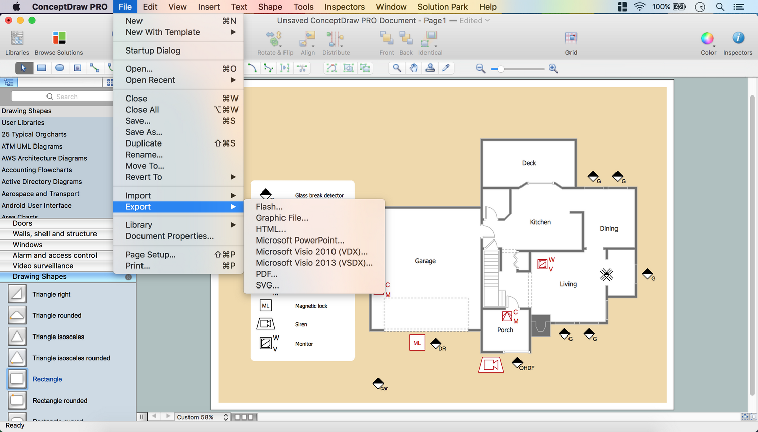
Picture: Security Plans
Related Solution:
This sample shows the Flowchart of the ACC general account creation. This Flowchart describes the Start point, the process of the handling the user requests and the End point – creating of the account. The shapes represent the subprocesses and the arrows between the shapes shows the sequence of the actions.
This sample was created in ConceptDraw DIAGRAM diagramming and vector drawing software using the Flowcharts solution from the Diagrams area of ConceptDraw Solution Park.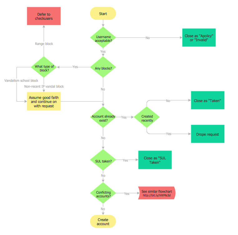
Picture: Examples of Flowchart
Related Solution:
At the base of the identity of an organisational is its organizational culture.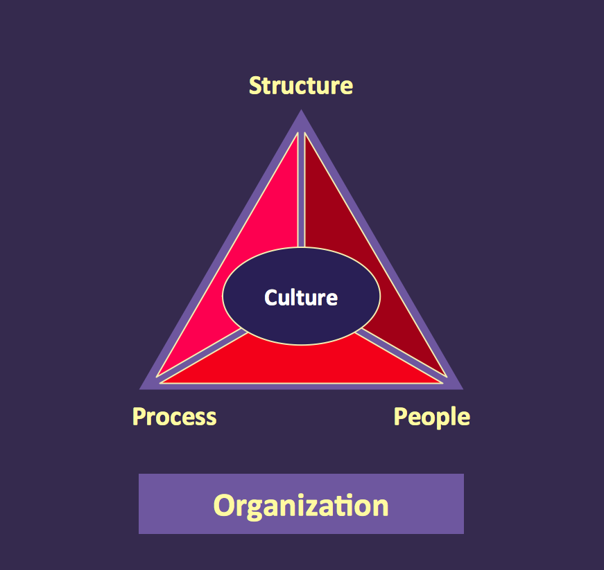
Picture: Pyramid Diagram
Related Solutions:
The ConceptDraw vector stencils library Cisco WAN contains equipment symbols for drawing the computer wide area network diagrams.
Picture: Cisco WAN. Cisco icons, shapes, stencils and symbols
Related Solution:
Unfortunately, a man can’t predict the future and no one is safe from natural disasters, such as floods, earthquakes, hurricanes or fires. Nonetheless, what you can do to ensure safety for you and your relatives is to create an emergency plan, so everyone will know what to do if emergency happens. Keep that plan simple and train it several times a year so that no one could forget any details of it.
Fire and emergency plans are important to supply people with a visual safety solution. This diagram presents a set of standard symbols used to depict fire safety, emergency, and associated information. Using clear and standard symbols on fire emergency plans provides the coherence of collective actions , helps to avoid embarrassment, and improves communications in an emergent situation. The fire emergency symbols are intended for the general emergency and fire service, as well as for building plans ,engineering drawings and insurance diagrams. They can be used during fire extinguishing and evacuation operations, as well as trainings. It includes vector symbols for emergency management mapping, emergency evacuation diagrams and plans.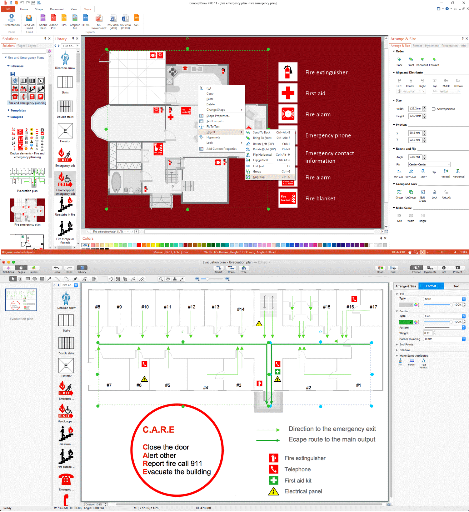
Picture: Emergency Plan
Related Solution:
The most convenient, useful and right way for software engineers, UI designers, UI developers is to use UI patterns in the process of developing any application for computer devices. The User Interface (UI) patterns are standardized solutions for common design problems.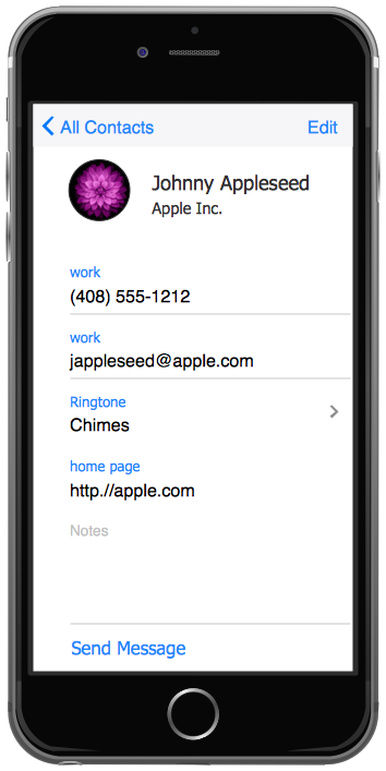
Picture: UI Patterns
Related Solution:
Cisco icons are globally recognized and generally accepted as standard for network icon topologies. The ConceptDraw vector stencils library Cisco buildings contains 21 symbols for drawing the computer network diagrams using the ConceptDraw DIAGRAM diagramming and vector drawing software.
Picture: Cisco Buildings. Cisco icons, shapes, stencils and symbols
Related Solution:

