"Microsoft SharePoint is a Web application platform developed by Microsoft. First launched in 2001, SharePoint has historically been associated with intranet, content management and document management, but recent versions have significantly broader capabilities.
SharePoint comprises a multipurpose set of Web technologies backed by a common technical infrastructure. By default, SharePoint has a Microsoft Office-like interface, and it is closely integrated with the Office suite. The web tools are designed to be usable by non-technical users. SharePoint can be used to provide intranet portals, document & file management, collaboration, social networks, extranets, websites, enterprise search, and business intelligence. It also has system integration, process integration, and workflow automation capabilities.
Enterprise application software (e.g. ERP or CRM packages) often provide some SharePoint integration capability, and SharePoint also incorporates a complete development stack based on web technologies and standards-based APIs. As an application platform, SharePoint provides central management, governance, and security controls for implementation of these requirements. The SharePoint platform integrates directly into IIS - enabling bulk management, scaling, and provisioning of servers, as is often required by large organizations or cloud hosting providers." [Microsoft SharePoint. Wikipedia]
The AWS architecture diagram example "SharePoint server reference architecture for public-facing website scenario" was created using the ConceptDraw PRO diagramming and vector drawing software extended with the AWS Architecture Diagrams solution from the Computer and Networks area of ConceptDraw Solution Park.
AWS architecture diagram

Creando Diagramas
 diagram - SharePoint server reference architecture for public facing website scenario")
 AWS Architecture Diagrams
The flexible AWS cloud solutions will help you to create reliable applications with a high level of scaling in the AWS cloud, to run your applications and accelerate their work on the level of security. Besides AWS resources are available worldwide and yo
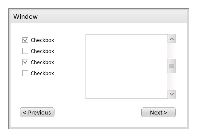
Use this template to prototype and design the wireframe graphic user interface (GUI).
"A website wireframe, also known as a page schematic or screen blueprint, is a visual guide that represents the skeletal framework of a website. Wireframes are created for the purpose of arranging elements to best accomplish a particular purpose. The purpose is usually being informed by a business objective and a creative idea. The wireframe depicts the page layout or arrangement of the website’s content, including interface elements and navigational systems, and how they work together. The wireframe usually lacks typographic style, color, or graphics, since the main focus lies in functionality, behavior, and priority of content. In other words, it focuses on what a screen does, not what it looks like. Wireframes can be pencil drawings or sketches on a whiteboard, or they can be produced by means of a broad array of free or commercial software applications. Wireframes are generally created by business analysts, user experience designers, developers, visual designers and other roles with expertise in interaction design, information architecture and user research.
Wireframes focus on:
(1) The kinds of information displayed.
(2) The range of functions available.
(3) The relative priorities of the information and functions.
(4) The rules for displaying certain kinds of information.
(5) The effect of different scenarios on the display.
The website wireframe connects the underlying conceptual structure, or information architecture, to the surface, or visual design of the website. Wireframes help establish functionality, and the relationships between different screen templates of a website. An iterative process, creating wireframes is an effective way to make rapid prototypes of pages, while measuring the practicality of a design concept. Wireframing typically begins between “high-level structural work - like flowcharts or site maps - and screen designs.” Within the process of building a website, wireframing is where thinking becomes tangible.
Aside from websites, wireframes are utilized for the prototyping of mobile sites, computer applications, or other screen-based products that involve human-computer interaction." [Website wireframe. Wikipedia]
The wireframe GUI template for the ConceptDraw PRO diagramming and vector drawing software is included in the Graphic User Interface solution from the Software Development area of ConceptDraw Solution Park.
Wireframe GUI template
 Data Flow Diagrams (DFD)
Data Flow Diagrams solution extends ConceptDraw PRO software with templates, samples and libraries of vector stencils for drawing the data flow diagrams (DFD).
This example of bank ATM UML activity diagram was created on the base of UML use case diagram of automated teller machine from the course "Thinking in Java, 2nd edition, Revision 9" by Bruce Eckel published on the website of the Computer Science and Electrical Engineering Department of the University of Maryland, Baltimore (UMBC).
"If you are designing an auto-teller, for example, the use case for a particular aspect of the functionality of the system is able to describe what the auto-teller does in every possible situation. Each of these “situations” is referred to as a scenario, and a use case can be considered a collection of scenarios. You can think of a scenario as a question that starts with: “What does the system do if...?” For example, “What does the auto-teller do if a customer has just deposited a check within the last 24 hours, and there’s not enough in the account without the check having cleared to provide a desired withdrawal?”
Use case diagrams are intentionally simple to prevent you from getting bogged down in system implementation details prematurely...
Each stick person represents an “actor,” which is typically a human or some other kind of free agent. (These can even be other computer systems, as is the case with “ATM.”) The box represents the boundary of your system. The ellipses represent the use cases, which are descriptions of valuable work that can be performed with the system. The lines between the actors and the use cases represent the interactions.
It doesn’t matter how the system is actually implemented, as long as it looks like this to the user."
[csee.umbc.edu/ courses/ 331/ resources/ tij/ text/ TIJ213.gif]
This automated teller machine (ATM) UML use case diagram example was created using the ConceptDraw PRO diagramming and vector drawing software extended with the ATM UML Diagrams solution from the Software Development area of ConceptDraw Solution Park.
Bank ATM UML sequence diagram

 Entity-Relationship Diagram (ERD)
Entity-Relationship Diagram (ERD) solution extends ConceptDraw PRO software with templates, samples and libraries of vector stencils from drawing the ER-diagrams by Chen's and crow’s foot notations.
- SharePoint server reference architecture for public-facing website ...
- Amazon Web Services | SharePoint server reference architecture for ...
- Architecture Of A Website Example
- AWS Architecture Diagrams | SharePoint server reference ...
- Web Hosting Infrastructure Diagram
- SharePoint server reference architecture for public-facing website
- Website launch - Flowchart | Website Wireframe | SharePoint server ...
- Amazon Web Services Diagrams diagramming tool for architecture ...
- AWS Architecture Diagrams | Diagramming tool - Amazon Web ...
- UML Use Case Diagram Example Social Networking Sites Project ...
- Website Wireframe | Safety and Security | Active Directory Diagrams ...
- Microsoft Azure reference architecture | SharePoint server reference ...
- Microsoft Azure reference architecture | SharePoint server reference ...
- Example Of A Web Hosting Architecture Diagram
- UML Use Case Diagram Example Social Networking Sites Project ...
- Website Wireframe | How to Develop Website Wireframes Using ...
- Amazon Web Services Diagrams diagramming tool for architecture ...
- Web Server Application Server Architecture Diagram
- Website Workflow