 Entity-Relationship Diagram (ERD)
Entity-Relationship Diagram (ERD) solution extends ConceptDraw PRO software with templates, samples and libraries of vector stencils from drawing the ER-diagrams by Chen's and crow’s foot notations.
HelpDesk
How to Create a Bank ATM Use Case Diagram

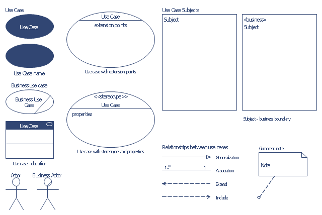
The vector stencils library "Bank UML use case diagram" contains 15 shapes for drawing UML use case diagrams.
Use it for object-oriented modeling of your bank information system.
"A use case diagram at its simplest is a representation of a user's interaction with the system that shows the relationship between the user and the different use cases in which the user is involved. A use case diagram can identify the different types of users of a system and the different use cases and will often be accompanied by other types of diagrams as well." [Use case diagram. Wikipedia]
This example of UML use case diagram symbols for the ConceptDraw PRO diagramming and vector drawing software is included in the ATM UML Diagrams solution from the Software Development area of ConceptDraw Solution Park.
UML use case diagram symbols
 Data Flow Diagrams (DFD)
Data Flow Diagrams solution extends ConceptDraw PRO software with templates, samples and libraries of vector stencils for drawing the data flow diagrams (DFD).
 Event-driven Process Chain Diagrams
Event-driven Process Chain (EPC) Diagram is a type of flowchart widely used for modeling in business engineering and reengineering, business process improvement, and analysis. EPC method was developed within the Architecture of Integrated Information Systems (ARIS) framework.
- Use Case Diagrams technology with ConceptDraw PRO | Jacobson ...
- UML Use Case Diagram Example. Services UML Diagram. ATM ...
- Use Case Diagrams technology with ConceptDraw PRO | UML ...
- Diagramming Software for Design UML Use Case Diagrams | UML ...
- UML Use Case Diagram Example. Services UML Diagram. ATM ...
- ATM UML Diagrams | UML Deployment Diagram Example - ATM ...
- UML Use Case Diagram Example Registration System | Financial ...
- UML Use Case Diagram Example. Services UML Diagram. ATM ...
- UML Diagram | How to Create a Bank ATM Use Case Diagram ...
- Jacobson Use Cases Diagram | Use case restaurant model | UML ...
- UML Use Case Diagram Example. Services UML Diagram. ATM ...
- ATM UML Diagrams | UML Use Case Diagram Example. Services ...
- Diagramming Software for Design UML Use Case Diagrams | UML ...
- UML Use Case Diagram Example. Services UML Diagram. ATM ...
- UML Use Case Diagram Example. Services UML Diagram. ATM ...
- UML Use Case Diagram Example. Services UML Diagram. ATM ...
- UML Use Case Diagram Example. Services UML Diagram. ATM ...
- UML Sequence Diagram Example. SVG Vectored UML Diagrams ...
- UML Use Case Diagram Example Registration System
- Diagramming Software for Design UML Use Case Diagrams ...