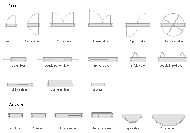
The design elements library Doors contains 69 symbols of doors.
The design elements library Windows contains 34 symbols of windows and casements.
"A door is an opening or closing structure used to block off an entrance, typically consisting of an interior side that faces the inside of a space and an exterior side that faces the outside of that space. While in some cases the interior side of a door may match its exterior side, in other cases there are sharp contrasts between the two sides, such as in the case of the vehicle door. In addition, doors typically consist of a panel that swings on hinges or that slides or spins inside of a space." [Door. Wikipedia]
"A window is an opening in a wall, door or vehicle that allows the passage of light and, if not closed or sealed, air and sound. Modern windows are usually glazed or covered in some other transparent or translucent material. Windows are held in place by frames. Many glazed windows may be opened, to allow ventilation, or closed, to exclude inclement weather." [Window. Wikipedia]
Use the shapes libraries Doors and Windows to create house plans, home plans, floor plan layouts and home designs using the ConceptDraw PRO diagramming and vector drawing software.
The vector stencils libraries Doors and Windows are provided by the Floor Plans solution from the Building Plans area of ConceptDraw Solution Park.
Doors and windows symbols
 Winter Sports
The Winter Sports solution from Sport area of ConceptDraw Solution Park contains winter sports illustration examples, templates and vector clipart libraries.
"Directional control valves route the fluid to the desired actuator. They usually consist of a spool inside a cast iron or steel housing. The spool slides to different positions in the housing, and intersecting grooves and channels route the fluid based on the spool's position. The spool has a central (neutral) position maintained with springs; in this position the supply fluid is blocked, or returned to tank. Sliding the spool to one side routes the hydraulic fluid to an actuator and provides a return path from the actuator to tank. When the spool is moved to the opposite direction the supply and return paths are switched. When the spool is allowed to return to neutral (center) position the actuator fluid paths are blocked, locking it in position. Directional control valves are usually designed to be stackable, with one valve for each hydraulic cylinder, and one fluid input supplying all the valves in the stack. Tolerances are very tight in order to handle the high pressure and avoid leaking, spools typically have a clearance with the housing of less than a thousandth of an inch (25 µm). The valve block will be mounted to the machine's frame with a three point pattern to avoid distorting the valve block and jamming the valve's sensitive components. The spool position may be actuated by mechanical levers, hydraulic pilot pressure, or solenoids which push the spool left or right. A seal allows part of the spool to protrude outside the housing, where it is accessible to the actuator. The main valve block is usually a stack of off the shelf directional control valves chosen by flow capacity and performance. Some valves are designed to be proportional (flow rate proportional to valve position), while others may be simply on-off. The control valve is one of the most expensive and sensitive parts of a hydraulic circuit." [Hydraulic machinery. Wikipedia]
The Windows template "Hydraulic 4-ported 3-position valve" for the ConceptDraw PRO diagramming and vector drawing software is included in the Mechanical Engineering solution from the Engineering area of ConceptDraw Solution Park.
www.conceptdraw.com/ solution-park/ engineering-mechanical
The Windows template "Hydraulic 4-ported 3-position valve" for the ConceptDraw PRO diagramming and vector drawing software is included in the Mechanical Engineering solution from the Engineering area of ConceptDraw Solution Park.
www.conceptdraw.com/ solution-park/ engineering-mechanical
Hydraulic directional control valve

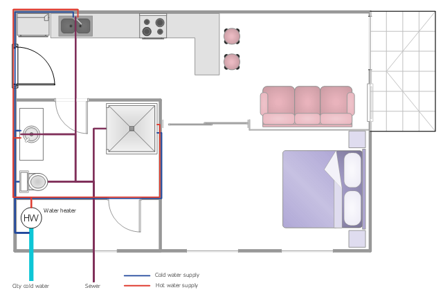
This plumbing and piping plan example shows the flat potable and hot water supply system.
"Potable water supply ... may come from several possible sources.
* Municipal water supply
* Water wells
* Processed water from creeks, streams, rivers, lakes, rainwater, etc. ...
Domestic hot water is provided by means of water heater appliances, or through district heating. The hot water from these units is then piped to the various fixtures and appliances that require hot water, such as lavatories, sinks, bathtubs, showers, washing machines, and dishwashers." [Tap water. Wikipedia]
The water supply scheme sample "Flat plumbing plan" was created using the ConceptDraw PRO diagramming and vector drawing software extended with the Plumbing and Piping Plans solution from the Building Plans area of ConceptDraw Solution Park.
Water supply system
- Gliding Window Drawing Symbols
- Sliding Window Drawing Symbols
- How To Draw Sliding Window On Building Drawing
- Sliding Glass Door How To Draw On Floor Plan
- Design elements - Doors and windows | Winter Sports | Sliding ...
- Design elements - Doors and windows | Electrical Drawing Software ...
- Design elements - Doors and windows | Mini Hotel Floor Plan. Floor ...
- Sliding Window Plan And Section
- Sliding Window Floor Plan
- Door Openings Plan Section Drawing
- Sliding Window Symbol In Floor Plan
- Sliding Door Floor Plan
- How To use House Electrical Plan Software | Visual Presentations ...
- Symbol Of Windows In Floor Plan
- Doors - Vector stencils library | Design elements - Doors and ...
- Design elements - Doors and windows
- Details Of Sliding Window On Floor Plan
- Symbol For Sliding Window In Floor Plan
- Sliding Window And Door Floor Plan