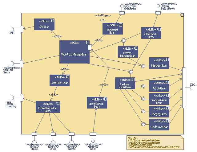
This UML sequence diagram of order processing center (OPC) was created on the base of sequence diagram from the software architecture documentation wiki of the Software Engineering Institute (SEI) of Carnegie Mellon University (CMU).
[wiki.sei.cmu.edu/ sad/ index.php/ Image:OPCRuntimeRefinementView_ PP2.png]
"Order processing is the process or work-flow associated with the picking, packing and delivery of the packed items to a shipping carrier. Order processing is a key element of order fulfillment. Order processing operations or facilities are commonly called "distribution centers"." [Order processing. Wikipedia]
This order processing center UML sequence diagram example was created using the ConceptDraw PRO diagramming and vector drawing software extended with the ATM UML Diagrams solution from the Software Development area of ConceptDraw Solution Park.
Order processing center UML sequence diagram
 Event-driven Process Chain Diagrams
Event-driven Process Chain (EPC) Diagram is a type of flowchart widely used for modeling in business engineering and reengineering, business process improvement, and analysis. EPC method was developed within the Architecture of Integrated Information Systems (ARIS) framework.
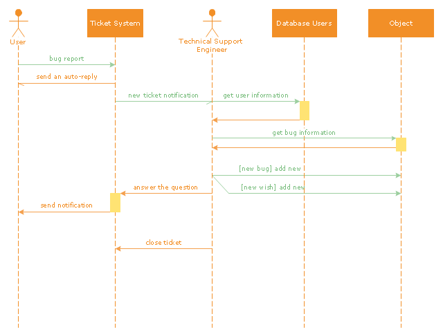
"An example scenario is presented to demonstrate how a common issue tracking system would work:
(1) A customer service technician receives a telephone call, email, or other communication from a customer about a problem. Some applications provide built-in messaging system and automatic error reporting from exception handling blocks.
(2) The technician verifies that the problem is real, and not just perceived. The technician will also ensure that enough information about the problem is obtained from the customer. This information generally includes the environment of the customer, when and how the issue occurs, and all other relevant circumstances.
(3) The technician creates the issue in the system, entering all relevant data, as provided by the customer.
(4) As work is done on that issue, the system is updated with new data by the technician. Any attempt at fixing the problem should be noted in the issue system. Ticket status most likely will be changed from open to pending.
(5) After the issue has been fully addressed, it is marked as resolved in the issue tracking system.
If the problem is not fully resolved, the ticket will be reopened once the technician receives new information from the customer. A Run Book Automation process that implements best practices for these workflows and increases IT personnel effectiveness is becoming very common." [Issue tracking system. Wikipedia]
The UML sequence diagram example "Ticket processing system" was created using the ConceptDraw PRO diagramming and vector drawing software extended with the Rapid UML solution from the Software Development area of ConceptDraw Solution Park.
UML sequence diagram
 Cross-Functional Flowcharts
Cross-functional flowcharts are powerful and useful tool for visualizing and analyzing complex business processes which requires involvement of multiple people, teams or even departments. They let clearly represent a sequence of the process steps, the order of operations, relationships between processes and responsible functional units (such as departments or positions).
 Rapid UML
Rapid UML solution extends ConceptDraw PRO software with templates, samples and libraries of vector stencils for quick drawing the UML diagrams using Rapid Draw technology.
- Order processing center - UML sequence diagram | Sequence ...
- UML Diagram | Purchase order processing UML activity diagram ...
- UML Sequence Diagram
- Order processing center - UML sequence diagram | Cross ...
- UML Diagram | Order processing center - UML sequence diagram ...
- Order processing center - UML sequence diagram | Event-driven ...
- Bank Sequence Diagram | UML Use Case Diagram Example ...
- UML Sequence Diagram
- UML Sequence Diagram | Diagramming Software for designing ...
- Draw Sequence Diagram For Order Processing System
- UML Sequence Diagram Example. SVG Vectored UML Diagrams ...
- UML Sequence Diagram | Design Elements for UML Diagrams ...
- Order processing center - UML sequence diagram
- Order processing - Cross-functional flowchart | Order processing ...
- Simplified Order Processing System Sequence Diagram
- Draw A Sequence And Collaboration Diagrams For Order Processing
- Purchase order processing UML activity diagram | Event-driven ...
- Credit Card Processing System UML Diagram
- Diagramming Software for designing UML Sequence Diagrams ...
- Purchase order processing UML activity diagram | Bank ATM use ...