"In electronics, a vacuum tube, electron tube (in North America), tube, or thermionic valve or valve (in British English) is a device controlling electric current through a vacuum in a sealed container. The simplest vacuum tube, the diode, contains only two elements; current can only flow in one direction through the device between the two electrodes, as electrons emitted by the hot cathode travel through the tube and are collected by the anode. Addition of a third and additional electrodes allows the current flowing between cathode and anode to be controlled in various ways. The device can be used as an electronic amplifier, a rectifier, an electronically controlled switch, an oscillator, and for other purposes.
Vacuum tubes mostly rely on thermionic emission of electrons from a hot filament or a cathode heated by the filament. Some electron tube devices rely on the properties of a discharge through an ionized gas." [Vacuum tube. Wikipedia]
"The EL34 is a thermionic valve or vacuum tube of the power pentode type. It has an international octal base (indicated by the '3' in the part number) and is found mainly in the final output stages of audio amplification circuits and was designed to be suitable as a series regulator by virtue of its high permissible voltage between heater and cathode and other parameters. The American RETMA tube designation number for this tube is 6CA7. Russian analog is 6P27S (Cyrillic: 6П27C )" [EL34. Wikipedia]
This circuit diagram sample was redrawn from the Wikipedia Commons file: EL34 schematics (circuit diagram).gif. [commons.wikimedia.org/ wiki/ File:EL34_ schematics_ %28circuit_ diagram%29.gif]
The example "Circuit diagram - EL 34 schematics" was drawn using the ConceptDraw PRO diagramming and vector drawing software extended with the Electrical Engineering solution from the Engineering area of ConceptDraw Solution Park.
EL34 shemathics

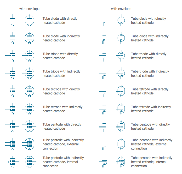
The vector stencils library "Design elements - Electron tubes" contains 36 element symbols of electron tubes.
Use it for drawing electrical schematics and electronic circuit diagrams.
"One classification of vacuum tubes is by the number of active electrodes, (neglecting the filament or heater). A device with two active elements is a diode, usually used for rectification. Devices with three elements are triodes used for amplification and switching. Additional electrodes create tetrodes, pentodes, and so forth, which have multiple additional functions made possible by the additional controllable electrodes.
Other classifications are:
(1) by frequency range (audio, radio, VHF, UHF, microwave),
(2) by power rating (small-signal, audio power, high-power radio transmitting),
(3) by design (e.g., sharp- versus remote-cutoff in some pentodes),
(4) by application (receiving tubes, transmitting tubes, amplifying or switching, rectification, mixing),
(5) special qualities (long life, very low microphonic and low noise audio amplification, and so on).
Multiple classifications may apply to a device; for example similar dual triodes can be used for audio preamplification and as flip-flops in computers, although linearity is important in the former case and long life in the latter.
Tubes have different functions, such as cathode ray tubes which create a beam of electrons for display purposes (such as the television picture tube) in addition to more specialized functions such as electron microscopy and electron beam lithography. X-ray tubes are also vacuum tubes. Phototubes and photomultipliers rely on electron flow through a vacuum, though in those cases electron emission from the cathode depends on energy from photons rather than thermionic emission." [Vacuum tube. Wikipedia]
The symbols example "Design elements - Electron tubes" was drawn using the ConceptDraw PRO diagramming and vector drawing software extended with the Electrical Engineering solution from the Engineering area of ConceptDraw Solution Park.
Vacuum tubes

The vector stencils library "Semiconductor diodes" contains 24 symbols of semiconductor diodes for drawing electronic schematics and circuit diagrams.
"In electronics, a diode is a two-terminal electronic component with asymmetric conductance; it has low (ideally zero) resistance to current in one direction, and high (ideally infinite) resistance in the other. A semiconductor diode, the most common type today, is a crystalline piece of semiconductor material with a p–n junction connected to two electrical terminals. A vacuum tube diode has two electrodes, a plate (anode) and a heated cathode. Semiconductor diodes were the first semiconductor electronic devices. ...
Today, most diodes are made of silicon, but other semiconductors such as selenium or germanium are sometimes used." [Diode. Wikipedia]
The shapes example "Design elements - Semiconductor diodes" was drawn using the ConceptDraw PRO diagramming and vector drawing software extended with the Electrical Engineering solution from the Engineering area of ConceptDraw Solution Park.
Semiconductor diode symbols

Electrical Symbols — Electron Tubes
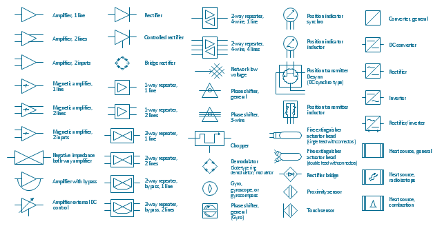
This vector stencils library contains 44 element symbols of transmitters (electronic amplifiers, repeaters), static devices (rectifiers), phase shift circuits, gyroscopes, and gyrators.
Use it to design the electronic circuit diagrams and electrical schematics.
"An electronic amplifier, amplifier, or (informally) amp is an electronic device that increases the power of a signal. It does this by taking energy from a power supply and controlling the output to match the input signal shape but with a larger amplitude. In this sense, an amplifier modulates the output of the power supply.
There are four basic types of electronic amplifier: the voltage amplifier, the current amplifier, the transconductance amplifier, and the transresistance amplifier. A further distinction is whether the output is a linear or exponential representation of the input. Amplifiers can also be categorized by their physical placement in the signal chain." [Amplifier. Wikipedia]
"A rectifier is an electrical device that converts Alternating Current (AC), which periodically reverses direction, to Direct Current (DC), which flows in only one direction. The process is known as rectification. Physically, rectifiers take a number of forms, including vacuum tube diodes, mercury-arc valves, copper and selenium oxide rectifiers, semiconductor diodes, silicon-controlled rectifiers and other silicon-based semiconductor switches." [Rectifier. Wikipedia]
"In telecommunications, a repeater is an electronic device that receives a signal and retransmits it at a higher level or higher power, or onto the other side of an obstruction, so that the signal can cover longer distances." [Repeater. Wikipedia]
"A phase shifter is a microwave network which provides a controllable phase shift of the RF signal. Phase shifters are used in phased arrays." [Phase shift module. Wikipedia]
"A vibrating structure gyroscope, standardised by IEEE as Coriolis vibratory gyroscope (CVG), is a wide group of gyroscope using solid-state resonators of different shapes that functions much like the halteres of an insect.
The underlying physical principle is that a vibrating object tends to continue vibrating in the same plane as its support rotates. In the engineering literature, this type of device is also known as a Coriolis vibratory gyro because as the plane of oscillation is rotated, the response detected by the transducer results from the Coriolis term in its equations of motion ("Coriolis force").
Vibrating structure gyroscopes are simpler and cheaper than conventional rotating gyroscopes of similar accuracy. Miniature devices using this principle are a relatively inexpensive type of attitude indicator." [Vibrating structure gyroscope. Wikipedia]
The example "Design elements - Composite assemblies" was drawn using the ConceptDraw PRO diagramming and vector drawing software extended with the Electrical Engineering solution from the Engineering area of ConceptDraw Solution Park.
Amplifiers, repeaters, rectifiers, phase shift circuits, gyroscopes, and gyrators
The vector stencils library "Logic gate diagram" contains 17 element symbols for drawing the logic gate diagrams.
"To build a functionally complete logic system, relays, valves (vacuum tubes), or transistors can be used. The simplest family of logic gates using bipolar transistors is called resistor-transistor logic (RTL). Unlike simple diode logic gates (which do not have a gain element), RTL gates can be cascaded indefinitely to produce more complex logic functions. RTL gates were used in early integrated circuits. For higher speed and better density, the resistors used in RTL were replaced by diodes resulting in diode-transistor logic (DTL). Transistor-transistor logic (TTL) then supplanted DTL. As integrated circuits became more complex, bipolar transistors were replaced with smaller field-effect transistors (MOSFETs); see PMOS and NMOS. To reduce power consumption still further, most contemporary chip implementations of digital systems now use CMOS logic. CMOS uses complementary (both n-channel and p-channel) MOSFET devices to achieve a high speed with low power dissipation." [Logic gate. Wikipedia]
The symbols example "Design elements - Logic gate diagram" was drawn using the ConceptDraw PRO diagramming and vector drawing software extended with the Electrical Engineering solution from the Engineering area of ConceptDraw Solution Park.
Logic gate symbols

- Vacuum Tube Circuit Diagrams
- Electrical Symbols — Electron Tubes | Circuit diagram - EL 34 ...
- Design elements - Electron tubes | Circuit diagram - EL 34 ...
- Vacuum Tube Symbol
- Design elements - Electron tubes | Electron tubes - Vector stencils ...
- Circuit diagram - EL 34 schematics | Electron tubes - Vector stencils ...
- Circuit diagram - EL 34 schematics | Circuit Diagram Of Pentode Valve
- Vacuum Tube Amplifier Schematics
- Electrical Drawing Software and Electrical Symbols | Design ...
- Design elements - Composite assemblies | Circuit diagram - EL 34 ...