Cloud Computing Architecture Diagrams

 Azure Architecture
Azure Architecture solution bundles into one handy tool everything you need to create effective Azure Architecture diagrams. It adds the extra value to versatile ConceptDraw DIAGRAM software and extends the users capabilities with comprehensive collection of Microsoft Azure themed graphics, logos, preset templates, wide array of predesigned vector symbols that covers the subjects such as Azure management, Azure storage, and Azure services, amongst others, and allow you to illustrate Azure Architecture diagrams at any degree of complexity, to present visually your Azure cloud system architecture with professional style, to design Azure cloud topology, to document Windows Azure Architecture and Azure Cloud System Architecture, to visualize the great abilities and work of Microsoft Azure Cloud System and Azure services.
Amazon Web Services
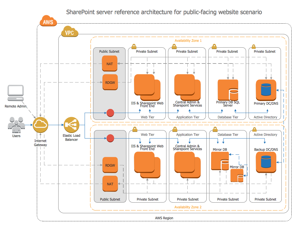
Network Components
This purchase order processing UML activity diagram was created on the base of activity diagram from the software architecture documentation wiki of the Software Engineering Institute (SEI) of Carnegie Mellon University (CMU).
[wiki.sei.cmu.edu/ sad/ index.php/ Image:PurchaseOrderActivityDiagram.png]
"A purchase order (PO) is a commercial document and first official offer issued by a buyer to a seller, indicating types, quantities, and agreed prices for products or services. Acceptance of a purchase order by a seller forms a contract between the buyer and seller, so no contract exists until the purchase order is accepted. It is used to control the purchasing of products and services from external suppliers.
Creating a purchase order is typically the first step of the purchase to pay process in an ERP system." [Purchase order. Wikipedia]
This purchase order processing UML activity diagram example was created using the ConceptDraw PRO diagramming and vector drawing software extended with the ATM UML Diagrams solution from the Software Development area of ConceptDraw Solution Park.
UML activity diagram of purchase order processing

- Sales Process Flowchart Symbols | Salesforce Sales Process Bpmn
- Sales Process Flowchart Symbols | Design elements - Sales KPIs ...
- Design elements - Sales KPIs and metrics | Salesforce Metric ...
- Sales Process Flowchart Symbols | Azure Architecture | Amazon ...
- Swim Lane Diagrams | Swim Lane Flowchart Symbols | Cross ...
- Invoice payment process - Flowchart | Purchase order processing ...
- Entity-Relationship Diagram (ERD) | Order process - BPMN 2.0 ...
- Business Process Management | Trouble ticket system - BPMN 2.0 ...
- KPIs and Metrics | Visualize Sales Data Using Sample Data | Sales ...
- Uml Activity Order Process Diagram Example