"In software engineering, software system safety optimizes system safety in the design, development, use, and maintenance of software systems and their integration with safety-critical hardware systems in an operational environment." [Software system safety. Wikipedia]
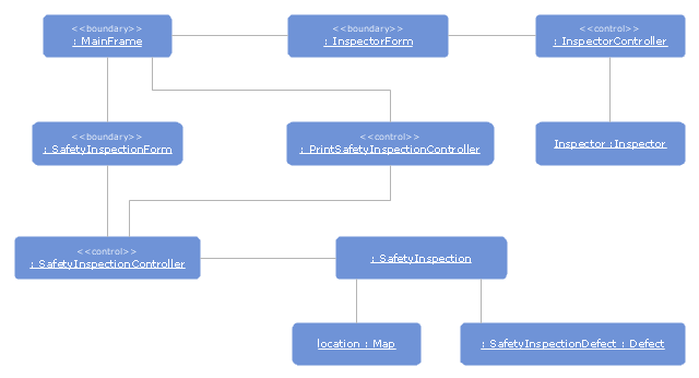
The UML object diagram example "Safety inspection" was created using the ConceptDraw PRO diagramming and vector drawing software extended with the Rapid UML solution from the Software Development area of ConceptDraw Solution Park.
The UML object diagram example "Safety inspection" was created using the ConceptDraw PRO diagramming and vector drawing software extended with the Rapid UML solution from the Software Development area of ConceptDraw Solution Park.
UML object diagram
This arrow loop diagram sample was created on the base of the figure illustrating the webpage "Safe Roads for a Safer Future A Joint Safety Strategic Plan" from the website of US Department of Transportation - Federal Highway Administration (FHWA) Office of Safety.
"STRATEGIC PLANNING CYCLE.
After the safety units issue the SSP, they will identify and prioritize strategies to support the established goals. Many strategies will originate in existing roadmaps or in other program planning activities. The safety units will also use this information when developing their Unit Performance Plans and individual performance plans. Teams within each safety unit will carry out projects and activities to support identified strategies and achieve the SSP goals.
The SSP process also includes continuous performance monitoring and evaluation through which the safety units will review past accomplishments against the established goals, consider how well strategies are implemented, assess progress toward goals, identify risks, consider changes in the environment, and discuss future strategic direction. As a part of the evaluation process, the three safety units will recognize achievements and discuss the need for adjustments. Figure ... shows the strategic planning cycle.
The safety units will update the SSP every 3 to 5 years using input from a variety of sources, including evaluations, safety trends, and legislative changes." [safety.fhwa.dot.gov/ ssp/ ]
The arrow loop diagram example "Strategic planning cycle" was created using the ConceptDraw PRO diagramming and vector drawing software extended with the Target and Circular Diagrams solution from the Marketing area of ConceptDraw Solution Park.
www.conceptdraw.com/ solution-park/ marketing-target-and-circular-diagrams
Arrow loop diagram
 Safety and Security
Safety and security solution extends ConceptDraw PRO software with illustration samples, templates and vector stencils libraries with clip art of fire safety, access and security equipment.
 Rapid UML
Rapid UML solution extends ConceptDraw PRO software with templates, samples and libraries of vector stencils for quick drawing the UML diagrams using Rapid Draw technology.
"A piping and instrumentation diagram/ drawing (P&ID) is a diagram in the process industry which shows the piping of the process flow together with the installed equipment and instrumentation. ...
P&IDs play a significant role in the maintenance and modification of the process that it describes. It is critical to demonstrate the physical sequence of equipment and systems, as well as how these systems connect. During the design stage, the diagram also provides the basis for the development of system control schemes, allowing for further safety and operational investigations, such as a Hazard Analysis and Operability Study...
For processing facilities, it is a pictorial representation of:
Key piping and instrument details,
Control and shutdown schemes,
Safety and regulatory requirements,
Basic start up and operational information." [Piping and instrumentation diagram. Wikipedia]
The piping and instrumentation diagram template for the ConceptDraw PRO diagramming and vector drawing software is included in the Chemical and Process Engineering solution from the Engineering area of ConceptDraw Solution Park.
Piping and instrumentation diagram / drawing (P&ID)
-piping-and-instrumentation-diagram-template.png--diagram-flowchart-example.png)
The vector clipart library Fire safety equipment contains 19 images of fire alarms, fire and smoke detectors, security cameras, and firefighting equipment.
Use the vector stencils library Fire safety equipment to draw the fire safety diagrams, firefighting equipment layout floor plans, and illustrations using the ConceptDraw PRO diagramming and vector drawing software.
"Fire safety refers to precautions that are taken to prevent or reduce the likelihood of a fire that may result in death, injury, or property damage, alert those in a structure to the presence of an uncontrolled fire in the event one occurs, better enable those threatened by fire to survive in and evacuate from affected areas, or to reduce the damage caused by a fire. Fire safety measures include those that are planned during the construction of a building or implemented in structures that are already standing, and those that are taught to occupants of the building.
Threats to fire safety are referred to as fire hazards. A fire hazard may include a situation that increases the likelihood a fire may start or may impede escape in the event a fire occurs." [Fire safety. Wikipedia]
The vector clipart example "Design elements - Fire safety equipment" is included in the Safety and Security solution from the Illustration area of ConceptDraw Solution Park.
Vector clip art

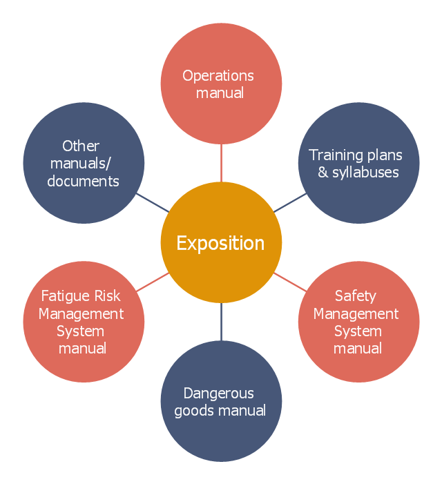
This circle-spoke diagram example was crated on the base of the illustration in the article "What is an exposition?" from the Civil Aviation Safety Authority (CASA) website.
"As the aviation industry transitions to new rules and safety standards through regulatory reform, organisations will be required to demonstrate to the Civil Aviation Safety Authority (CASA) how they have met the requirements outlined in the legislation, including the regulations and manual of standards applicable to their operation through a document called an exposition.
An exposition is a description of how organisations will conduct their operations to maintain the required level of safety. The exposition is the primary document, supported by a series of manuals, such as the operations manual and safety management system manual. These manuals and other supporting documents form part of the exposition document set, as shown in the ... diagram." [casa.gov.au/ scripts/ nc.dll?WCMS:STANDARD::pc=PC_ 101706]
The hub-and-spoke diagram example "CASA exposition" was created using the ConceptDraw PRO diagramming and vector drawing software extended with the Circle-Spoke Diagrams solution from the area "What is a Diagram" of ConceptDraw Solution Park.
Circle-spoke diagram
- Diagram Of Safety Equipment
- UML object diagram - Safety inspection | Diagramming Software for ...
- Diagram Of Some Safety Equipments
- Fire Safety Diagram
- Entity-Relationship Diagram (ERD) | Safety and Security | Account ...
- Emergency Plan | Safety and Security | UML Tool & UML Diagram ...
- Diagram Of Fire Safety Equipment
- Safety and Security | Fire safety equipment - Vector stencils library ...
- UML Tool & UML Diagram Examples | Draw In Good Road Safe ...
- Safety Equipments And Pictures Showing Their Diagram
- Fishbone Diagram Product Safety Example
- Design elements - Fire safety equipment | Fire Precautions Diagram
- Road Safety Diagrams
- Safety and Security | Food Court | AWS Architecture Diagrams ...
- Safety Pyramid Diagram
- Diagram Of Different Safety Equipments
- Level Diagram Structure Of Safety Department
- Piping and instrumentation diagram template | Piping and ...
- Fire and Emergency Plans | Emergency Plan | Safety and Security ...
- Safety Valve Diagram