A simple hydraulic schematic showing apparatus for testing the strength of a hydraulic hose splice.
Water enters through normally closed solenoid valve (1) and passes through intake flow meter (2) to high pressure pump (4). Intake water pressure is monitored by pressure gauge (3). The hose to be tested connects between pump (4) and normally open solenoid activated drain valve (7). To test the hose, pump drive motor (5) is turned on, the solenoid of drain valve (7) is activated, closing the valve, and the pump is run to pressurize the hose. Test pressure is monitored by gauge (6). When the test is complete or the hose fails, the solenoid of drain valve (7) is deactivated, opening valve and discharging water, depressurizing the system. All components are operated electrically by a remote control circuit so that the operator may perform the test from a protected location, monitoring it with a camera and video monitor.
This hydraulic schematic example was redrawn using ConceptDraw PRO diagramming and vector drawing software from the Wikimedia Commons file: Hydraulic schematic.jpg.
[commons.wikimedia.org/ wiki/ File:Hydraulic_ schematic.jpg]
This file is licensed under the Creative Commons Attribution-Share Alike 3.0 Unported license.
[creativecommons.org/ licenses/ by-sa/ 3.0/ deed.en]
The hydraulic schematic example "Apparatus for testing the strength of a hydraulic hose splice" is included in the Mechanical Engineering solution from the Engineering area of ConceptDraw Solution Park.
Hydraulic system schematic

 Mechanical Engineering
This solution extends ConceptDraw PRO v.9 mechanical drawing software (or later) with samples of mechanical drawing symbols, templates and libraries of design elements, for help when drafting mechanical engineering drawings, or parts, assembly, pneumatic,
"Directional control valves are one of the most fundamental parts in hydraulic machinery as well and pneumatic machinery. They allow fluid flow into different paths from one or more sources. They usually consist of a spool inside a cylinder which is mechanically or electrically controlled. The movement of the spool restricts or permits the flow, thus it controls the fluid flow. ...
While working with layouts of hydraulic machinery it is cumbersome to draw actual picture of every valve and other components.instead of pictures symbols are used for variety of components in the hydraulic system to highlight the functional aspects. symbol for directional control valve is made of number of square boxes adjacent to each other depending on the number of positions.connections to the valve are shown on these squares by capital letters.usually they are named only in their normal position and not repeated in other positions.actuation system of the valve is also designated in its symbol." [Directional control valve. Wikipedia]
The Mac template "Pneumatic 5-ported 3-position valve" for the ConceptDraw PRO diagramming and vector drawing software is included in the Mechanical Engineering solution from the Engineering area of ConceptDraw Solution Park.
www.conceptdraw.com/ solution-park/ engineering-mechanical
Pneumatic directional control valve

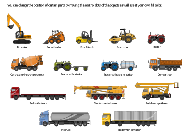
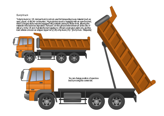
"Heavy equipment refers to heavy-duty vehicles, specially designed for executing construction tasks, most frequently ones involving earthwork operations. They are also known as, heavy machines, heavy trucks, construction equipment, engineering equipment, heavy vehicles, or heavy hydraulics." [Heavy equipment.
Wikipedia]
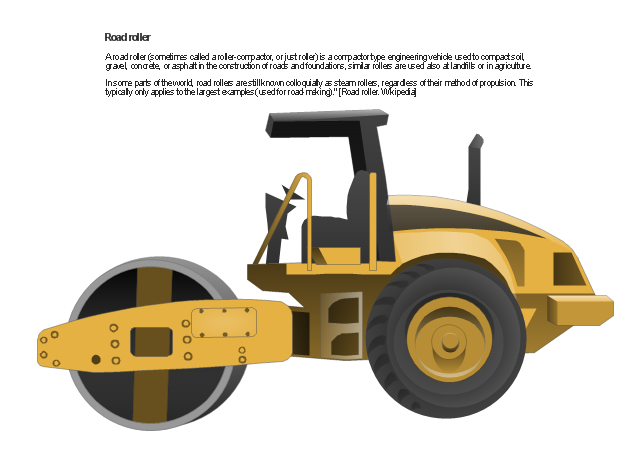
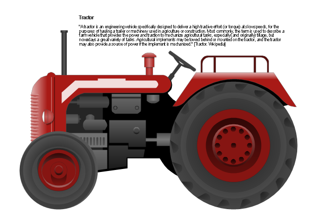
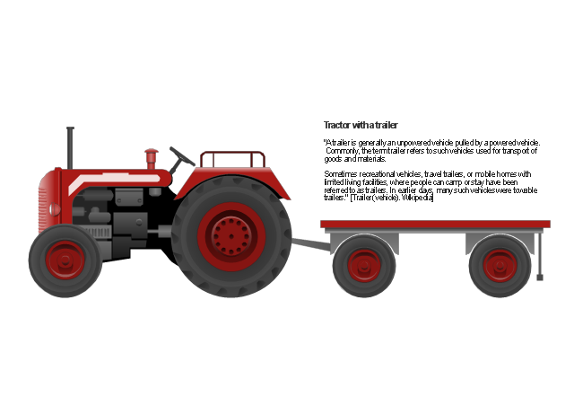
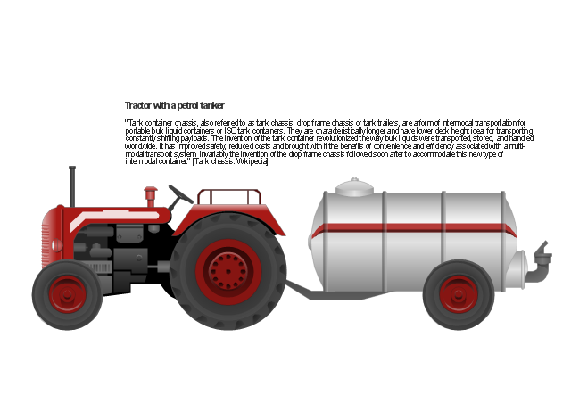
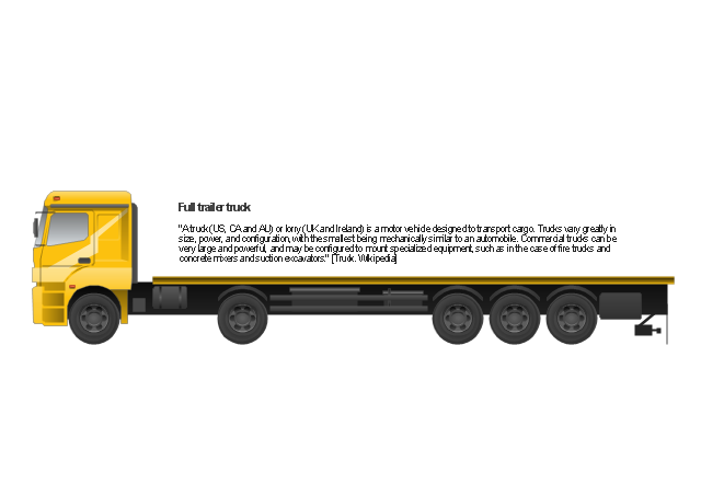
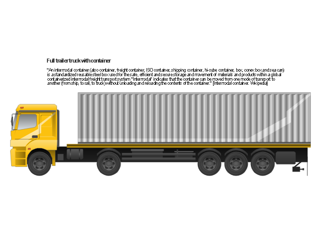
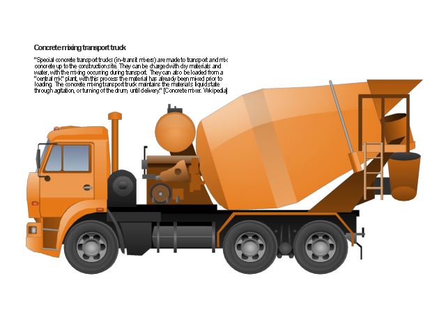
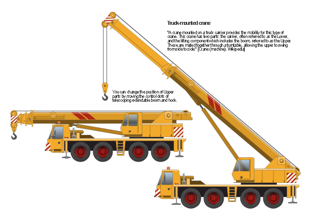
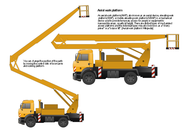
The vector stencils library "Industrial vehicles" for the ConceptDraw PRO diagramming and vector drawing software includes 14 images of heavy-duty vehicles: excavator, bucket loader, forklift truck, road roller, tractor, tractor with a trailer, tractor with a petrol tanker, dumper truck, full trailer truck, trailer with container, tank truck, concrete mixing transport truck, truck-mounted crane, aerial work platform.
The vector clipart library "Industrial vehicles" is included in the Manufacturing and Maintenance solution from the Illustration area of ConceptDraw Solution Park.
Wikipedia]
The vector stencils library "Industrial vehicles" for the ConceptDraw PRO diagramming and vector drawing software includes 14 images of heavy-duty vehicles: excavator, bucket loader, forklift truck, road roller, tractor, tractor with a trailer, tractor with a petrol tanker, dumper truck, full trailer truck, trailer with container, tank truck, concrete mixing transport truck, truck-mounted crane, aerial work platform.
The vector clipart library "Industrial vehicles" is included in the Manufacturing and Maintenance solution from the Illustration area of ConceptDraw Solution Park.
Industrial vehicles
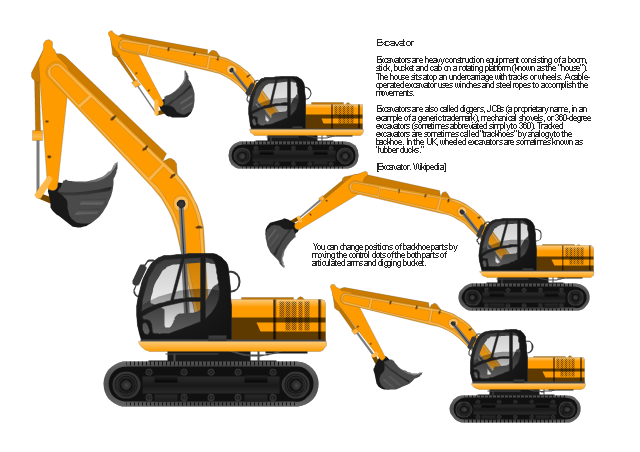
Excavator
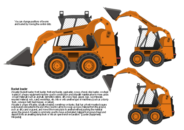
Bucket loader
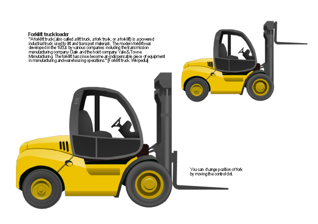
Forklift truck
Road roller
Tractor
Tractor with a trailer
Tractor with a petrol tanker
Dumper truck
Full trailer truck
Trailer with container
Tank truck

Concrete mixing transport truck
Truck-mounted crane
Aerial work platform
- Open Source Schematic Software
- Hydraulic schematic | Hydraulic 4-ported 3-position valve template ...
- Technical Drawing Software | Hydraulic Circuit For Hydraulic Planner
- Draw A Circuit Diagram Of A Hydraulic Engineering System
- Mechanical Engineering | Comparison Hydraulic Electric Symbols
- Open Source Network Diagramming Tool
- Hydraulic schematic
- Open Source Drawing Software
- Microsoft Visio Open Source
- SysML | Data Flow Diagrams | Stakeholder Onion Diagrams ...
- Open Source Agile Project Management
- Technical Drawing Software | Mechanical Drawing Symbols ...
- Best Open Source Software Swim Lanes
- Open Source Visio Equivalent
- Open Source Visio Editor
- Er Diagram Software Open Source
- Plant Layout Plans | Piping and Instrumentation Diagram Software ...
- Open Source Flowchart Software
- Open Source Mockup Tool
- Visio Editor Open Source