Program Structure Diagram
Program Structure Diagram - The Software Development solution from ConceptDraw Solution Park provides the stensils libraries of language level shapes and memory objects for drawing the structural diagrams of programs and memory objects using the ConceptDraw PRO diagramming and vector drawing software.HelpDesk
How to Create an ERD Diagram
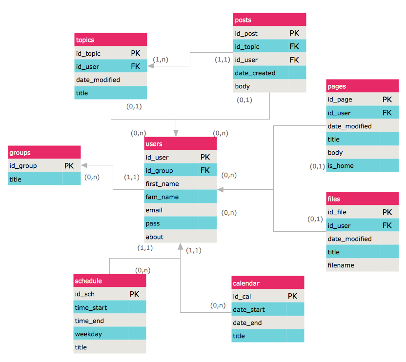
ERD (entity relationship diagram) is used to show the logical structure of databases. It represents the interrelationships between components of database (entities). Entity relationship diagrams are a widely used in software engineering. Using ERD software engineers can control the every aspect of database development. ER diagram can be used as guide for testing and communicating before the release of software product. ERD displays data as entities that are connected with connections that show the relationships between entities. There is some ERD notations used by data bases developers for representing the relationships between the data objects. ConceptDraw PRO and its ERD solution allow you to build ERD diagram of any notation.
 Entity-Relationship Diagram (ERD)
An Entity-Relationship Diagram (ERD) is a visual presentation of entities and relationships. That type of diagrams is often used in the semi-structured or unstructured data in databases and information systems. At first glance ERD is similar to a flowch
 Note Exchange
This solution extends ConceptDraw MINDMAP software with the ability to exchange with Evernote, and access mind maps anywhere, on any computer or mobile device via Evernote.
Overlay network. Computer and Network Examples
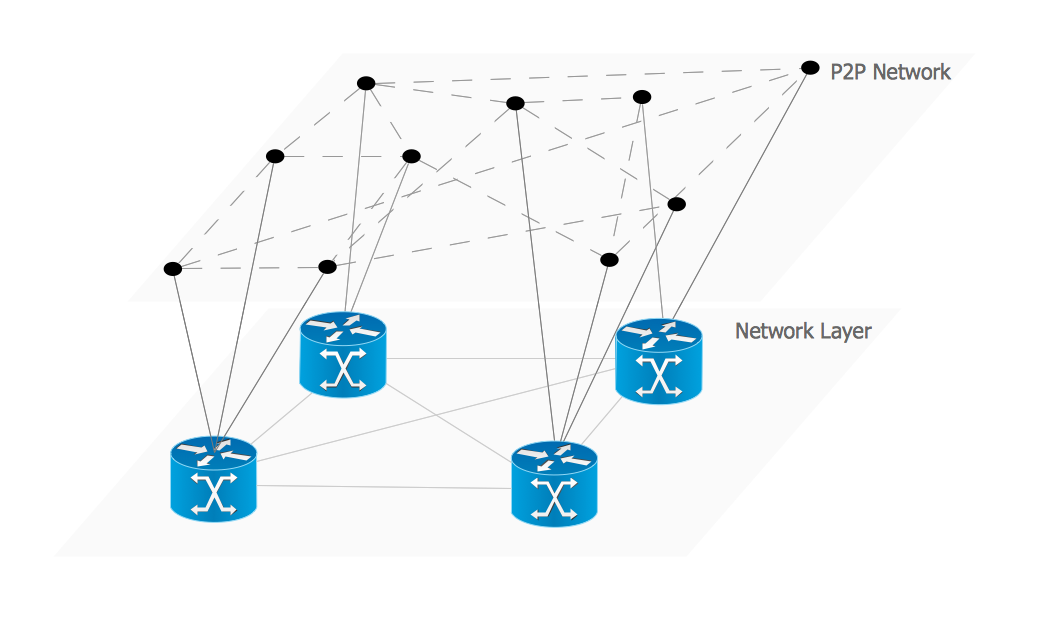
An Overlay network is a computer network that is built on the top of another network. The nodes of the overlay network are connected by virtual or logical links. This example was created in ConceptDraw PRO using the Computer and Networks Area of ConceptDraw Solution Park and shows the Overlay network diagram for the P2P network.
- Block diagram - Document management system architecture ...
- Flow chart Example. Warehouse Flowchart | Identifying Quality ...
- Process Flowchart | Block diagram - Document management system ...
- Block diagram - Document management system architecture | Block ...
- Block diagram - Document management system architecture | Block ...
- Block diagram - Document management system architecture | Block ...
- Block diagram - Document management system architecture | Block ...
- Process Flowchart | Block Diagram | Block diagram - Document ...
- Flow chart Example. Warehouse Flowchart | Data Flow Diagram ...
- Block diagram - Document management system architecture | Block ...
- Process Flowchart | UML Package Diagram. Design Elements | Data ...
- Block diagram - Document management system architecture | Block ...
- Flow chart Example. Warehouse Flowchart | How to Update ...
- Engineering | Example of DFD for Online Store (Data Flow Diagram ...
- Block diagram - Document management system architecture ...
- Block diagram - Document management system architecture ...
- Pyramid Diagram | Process Flowchart | Block diagram - Document ...
- Block Diagrams | How to Draw a Block Diagram in ConceptDraw ...
- Block Diagrams | Block Diagram | Computer Network Architecture ...
- Process Flowchart | Functional Block Diagram | Flow chart Example ...


