Overlay network.
Computer and Network Examples
An Overlay network is a computer network that is built on the top of another network. The nodes of the overlay network are connected by virtual or logical links.
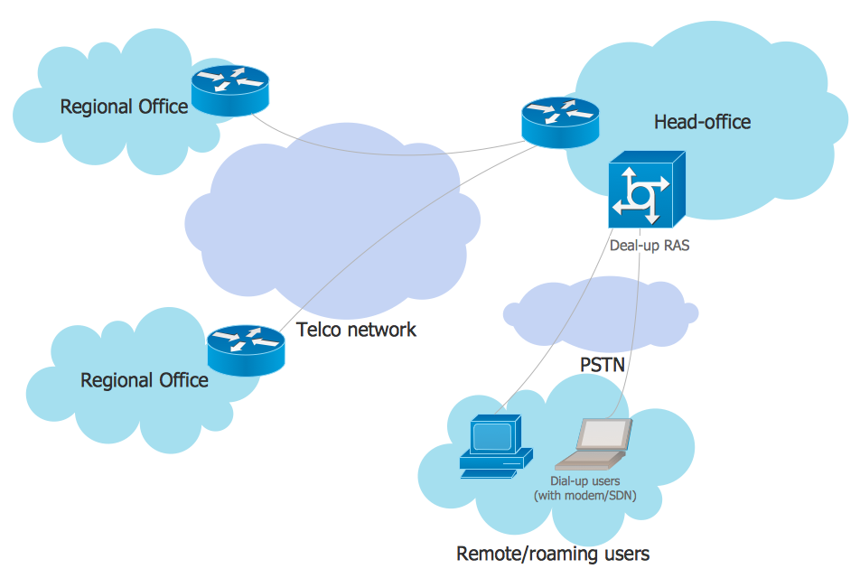
This example was created in ConceptDraw DIAGRAM using the Computer and Networks Area of ConceptDraw Solution Park and shows the Overlay network diagram for the P2P network.

Example 1. Computer and Network Area.
Peer-to-peer (P2P) network is a virtual overlay network on top of the physical network topology. In the overlay its nodes form the subset of the nodes in the physical network. The nodes are equal peer nodes. At the application layers the peers exchange data via the logical overlay links. Overlays are used for indexing and peer discovery. They also make the P2P system independent from the physical network topology. The networks can be structured and unstructured in depending on how the nodes are linked each other.
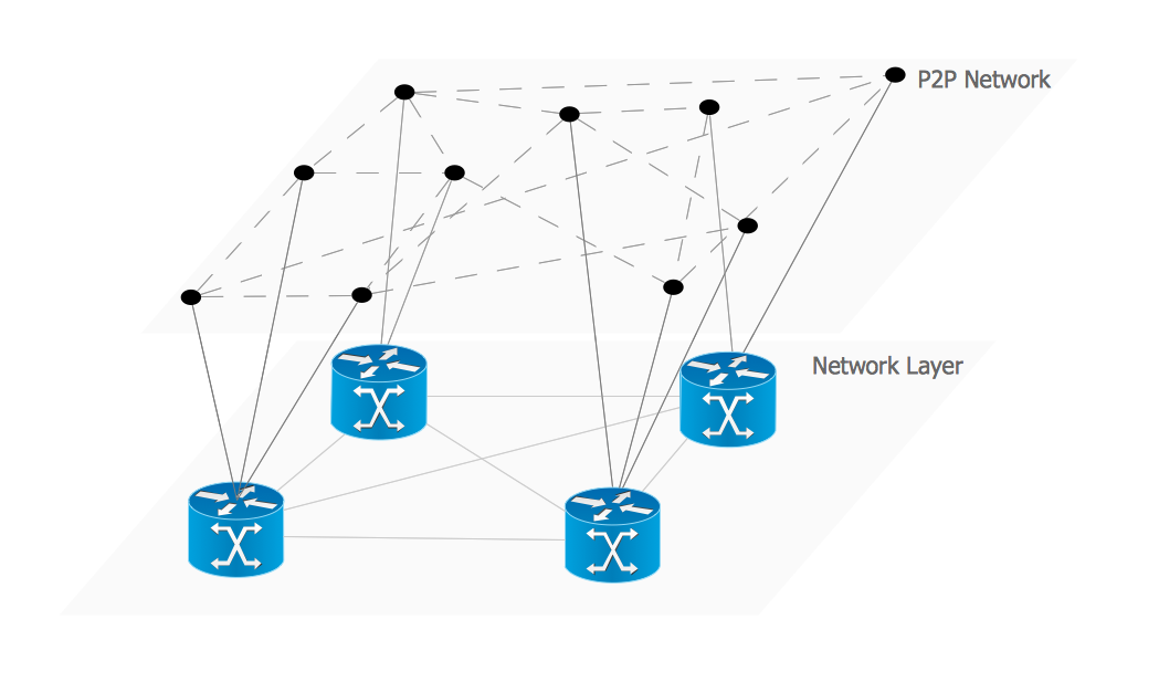
Example 2. Overlay network.
This example was redesigned from the file [https://commons.wikimedia.org]
Using the solutions of the Computer and Networks Area for ConceptDraw DIAGRAM you can design anyone overlay networks quick and easy.
The diagrams created with ConceptDraw DIAGRAM are vector graphic documents and are available for reviewing, modifying, and converting to a variety of formats (image, HTML, PDF file, MS PowerPoint Presentation, Adobe Flash or MS Visio).
See also Samples: