"Geometric dimensioning and tolerancing (GD&T) is a system for defining and communicating engineering tolerances. It uses a symbolic language on engineering drawings and computer-generated three-dimensional solid models that explicitly describes nominal geometry and its allowable variation. It tells the manufacturing staff and machines what degree of accuracy and precision is needed on each controlled feature of the part. GD&T is used to define the nominal (theoretically perfect) geometry of parts and assemblies, to define the allowable variation in form and possible size of individual features, and to define the allowable variation between features." [Geometric dimensioning and tolerancing. Wikipedia]
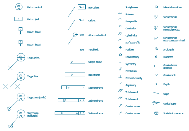
The vector stencils library Dimensioning and tolerancing contains 45 symbols to indicate geometric dimensions and mechanical tolerances. It also includes geometric symbols, callouts, and text boxes and inserts. Use it to create annotated mechanical drawings.
This symbols library for ConceptDraw PRO diagramming and vector drawing software is contained in the Mechanical Engineering solution from ConceptDraw Solution Park. www.conceptdraw.com/ solution-park/ engineering-mechanical
Page1
- GUI Prototyping with ConceptDraw PRO | Cross-Functional ...
- ER diagram tool for OS X | Best Vector Drawing Application for Mac ...
- What is SWOT Analysis? | SWOT analysis matrix diagram templates ...
- Engineering | Mechanical Engineering | Universal Diagramming Area |
- How to Draw an Organization Chart | Enhancing maps using ...
- Entity-Relationship Diagram (ERD) | ConceptDraw Solution Park ...
- ConceptDraw PRO Compatibility with MS Visio
- Matrices | Seven Management and Planning Tools | Feature ...