The vector stencils library "Dimensioning and tolerancing" contains 45 symbols of geometric dimensions and mechanical tolerances, geometric symbols, callouts, and text boxes and inserts.
Use these geometric dimensioning and tolerancing (GD&T) shapes to create annotated mechanical drawings.
"Geometric dimensioning and tolerancing (GD&T) is a system for defining and communicating engineering tolerances. It uses a symbolic language on engineering drawings and computer-generated three-dimensional solid models that explicitly describes nominal geometry and its allowable variation. It tells the manufacturing staff and machines what degree of accuracy and precision is needed on each controlled feature of the part. GD&T is used to define the nominal (theoretically perfect) geometry of parts and assemblies, to define the allowable variation in form and possible size of individual features, and to define the allowable variation between features." [Geometric dimensioning and tolerancing. Wikipedia]
The shapes example "Design elements - Dimensioning and tolerancing" was created using the ConceptDraw PRO diagramming and vector drawing software extended with the Mechanical Engineering solution from the ConceptDraw Solution Park.
HelpDesk
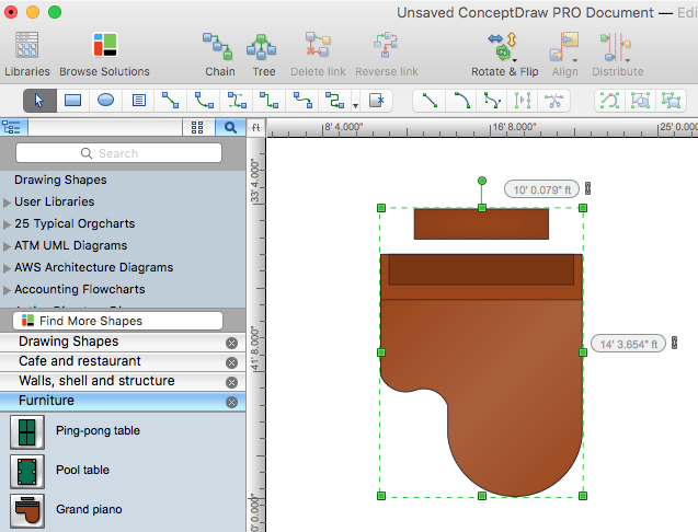
How to Change Measurement Units in ConceptDraw Drawing
ConceptDraw PRO allows you to work with drawings with many different measurement units.HelpDesk
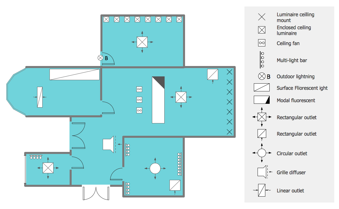
How to Create a Reflected Ceiling Floor Plan
A Reflected Ceiling Plan (RCP) is a drawing of a room or building, looking down at the interior ceiling. Making RCP involves many different reflected ceiling plan symbols that can be managed using ConceptDraw PRO. Using ConceptDraw PRO you can design the reflected ceiling floor plan that shows the location of light fixtures and any other items that may be suspended from the ceiling. You can share your ceiling design ideas by saving drawings as graphics files, or printing them.HelpDesk
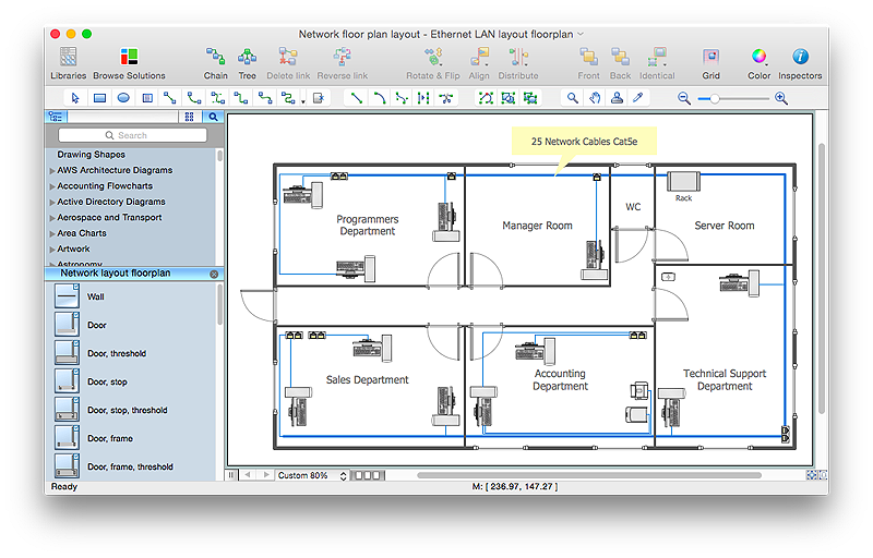
How to Create a Network Layout Floor Plan
With technology and market forces demanding ever quicker business response times, a well-structured computer network is the foundation of positive communication between employees, and with the wider world. When you walk into most modern work offices, there is a good chance you will be greeted by banks of computer screens and terminals, perhaps some sales points screens or server stacks, almost certainly routers and printers. A side effect of this amount of hardware is the amount of cabling necessary to connect these elements into an effective local area network (LAN). This is the idea behind a network layout plan - it can show how a network is connected, how data transfers between those connections, and give an overview of devices and hardware used in office. To create a practical computer network floor plan, the network administrator must adhere to the specified requirements and limitations of the office or building in which the LAN will operate - things such as hardware availability,- Symbol Dimensioning According To Engineering Drawing
- Engineering Drawing Dimension Symbols
- Mechanical Drawing Symbols | Design elements - Bearings | Design ...
- Mechanical Drawing Symbols | Design elements - Dimensioning ...
- Mechanical Engineering | Design elements - Bearings | Design ...
- Elements location of a welding symbol | Building Drawing
- Mechanical Drawing Symbols | Design elements - Dimensioning ...
- Mechanical Design Symbols Used In Parts Design
- Mechanical Drawing Symbols | Design elements - Dimensioning ...
- Mechanical Drawing Symbols | Design elements - Dimensioning ...
- Mechanical Drawing Symbols | Basic Flowchart Symbols and ...
- Mechanical Engineering | How to Create a Mechanical Diagram ...
- Mechanical Drawing Symbols | Mechanical Engineering ...
- Mechanical Drawing Symbols | Basic Flowchart Symbols and ...
- Mechanical Drawing Symbols | Engineering | Design elements ...
- Mechanical Machine Parts Explained Drawings
- Mechanical Drawing Symbols | Engineering | Process Flowchart ...
- Mechanical Drawing Symbols | Mechanical Drawing Software ...
- Mechanical Engineering Drawing Parts
- Mechanical Engineering Drawing Symbols Pdf


