Network Diagram Software


 Electrical Engineering
This solution extends ConceptDraw DIAGRAM.9.5 (or later) with electrical engineering samples, electrical schematic symbols, electrical diagram symbols, templates and libraries of design elements, to help you design electrical schematics, digital and analog
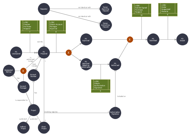
This IDEF3 diagram example was redesigned from the Wikimedia Commons file: 2-03 Example of an Enhanced Transition Schematic.jpg.
[en.wikipedia.org/ wiki/ File:2-03_ Example_ of_ an_ Enhanced_ Transition_ Schematic.jpg]
"IDEF3 descriptions are developed from two different perspectives: process-centered and object-centered. Because these approaches are not mutually exclusive, IDEF3 allows cross-referencing between them to represent complex process descriptions." [IDEF3. Wikipedia]
The IDEF3 diagram example "Enhanced transition schematic" was created using the ConceptDraw PRO diagramming and vector drawing software extended with the solution "IDEF Business Process Diagrams" from the area "Business Processes" of ConceptDraw Solution Park.
IDEF3 business process diagram
- Electrical Drawing Software and Electrical Symbols | How To use ...
- Sample Diagram In Electrical Engineering
- Schematic Diagram Diagram Sample
- How to Create an Electrical Diagram Using ConceptDraw PRO ...
- Process Flowchart | Flow chart Example . Warehouse Flowchart ...
- Schematic Diagram For Purchase Order
- Flow chart Example . Warehouse Flowchart | Schematic Diagram Of ...
- Schematic Diagram Of Gprs
- Lan Schematic Diagrams
- Telecommunication networks. Computer and Network Examples ...
- Wiring Diagrams with ConceptDraw PRO | Wiring Diagram Floor ...
- Sample Schematic Parking Map
- Bipolar current mirror - Circuit diagram | Amplifier - Circuit diagram ...
- Basic CCTV System Diagram . CCTV Network Diagram Example ...
- Business Schematic Diagram Software
- Schematic Diagram Of A Call Centre
- Network Diagram Examples | Network Topology | Hotel Network ...
- Process Flowchart | Flow chart Example . Warehouse Flowchart ...
- Process Flowchart | Block Diagram Creator | Flow chart Example ...
- Flow chart Example . Warehouse Flowchart | Process Flowchart ...