The vector stencils library "Fluid power equipment" contains 113 symbols of hydraulic and pneumatic equipment including pumps, motors, air compressors, cylinders, meters, gauges, and actuators. Use it to design fluid power and hydraulic control systems.
"Fluid power is the use of fluids under pressure to generate, control, and transmit power. Fluid power is subdivided into hydraulics using a liquid such as mineral oil or water, and pneumatics using a gas such as air or other gases. Compressed-air and water-pressure systems were once used to transmit power from a central source to industrial users over extended geographic areas; fluid power systems today are usually within a single building or mobile machine." [Fluid power. Wikipedia]
The shapes example "Design elements - Fluid power equipment" was created using the ConceptDraw PRO diagramming and vector drawing software extended with the Mechanical Engineering solution from the Engineering area of ConceptDraw Solution Park.
Fluid power symbols

 Mechanical Engineering
This solution extends ConceptDraw PRO v.9 mechanical drawing software (or later) with samples of mechanical drawing symbols, templates and libraries of design elements, for help when drafting mechanical engineering drawings, or parts, assembly, pneumatic,
This example engineering drawing showing the hydraulic directional control valve usage with floating motor and pressure compensated pump is redesigned using the ConceptDraw PRO diagramming and vector drawing software from the Wikimedia Commons file: DCV 17.jpg.
[commons.wikimedia.org/ wiki/ File:DCV_ 17.jpg]
This file is licensed under the Creative Commons Attribution-Share Alike 3.0 Unported license.
[creativecommons.org/ licenses/ by-sa/ 3.0/ deed.en]
"Directional control valves are one of the most fundamental parts in hydraulic machinery as well and pneumatic machinery. They allow fluid flow into different paths from one or more sources. They usually consist of a spool inside a cylinder which is mechanically or electrically controlled. The movement of the spool restricts or permits the flow, thus it controls the fluid flow. ...
The spool (sliding type) consists of lands and grooves.The lands block oil flow through the valve body. The grooves allow oil or gas to flow around the spool and through the valve body. There are two fundamental positions of directional control valve namely normal position where valve returns on removal of actuating force and other is working position which is position of a valve when actuating force is applied. There is another class of valves with 3 or more position that can be spring centered with 2 working position and a normal position. ...
Directional control valves can be classified according to:
(1) number of ports;
(2) number of positions;
(3) actuating methods;
(4) type of spool." [Directional control valve. Wikipedia]
The fluid power equipment drawing example "Directional control valve" is included in the Mechanical Engineering solution from the Engineering area of ConceptDraw Solution Park.
Hydraulic equipment schematic

 Engineering
This solution extends ConceptDraw PRO v9.4 with the ability to visualize industrial systems in electronics, electrical, chemical, process, and mechanical engineering.
"Directional control valves are one of the most fundamental parts in hydraulic machinery as well and pneumatic machinery. They allow fluid flow into different paths from one or more sources. They usually consist of a spool inside a cylinder which is mechanically or electrically controlled. The movement of the spool restricts or permits the flow, thus it controls the fluid flow." [Directional control valve. Wikipedia]
This example engineering drawing showing the directional control valve usage with fixed volume pump and hydraulic cylinder is redesigned using the ConceptDraw PRO diagramming and vector drawing software from Wikimedia Commons file: DCV 19.jpg.
[commons.wikimedia.org/ wiki/ File:DCV_ 19.jpg]
This file is licensed under the Creative Commons Attribution-Share Alike 3.0 Unported license.
[creativecommons.org/ licenses/ by-sa/ 3.0/ deed.en]
The fluid power equipment drawing example "Directional control valve" is included in the Mechanical Engineering solution from the Engineering area of ConceptDraw Solution Park.
Hydraulic equipment schematic

HelpDesk
How to Create a Mechanical Diagram

The vector stencils library "Tools" contains 11 clipart images of hand tools and instruments for drawing illustrations.
"A tool is any physical item that can be used to achieve a goal, especially if the item is not consumed in the process. Informally the word is also used to describe a procedure or process with a specific purpose. Tool use by humans dates back millions of years, and other animals are also known to employ simple tools.
Tools that are used in particular fields or activities may have different designations such as "instrument", "utensil", "implement", "machine", or "apparatus". The set of tools needed to achieve a goal is "equipment". The knowledge of constructing, obtaining and using tools is technology." [Tool. Wikipedia]
The clip art example "Tools - Vector stencils library" was created in ConceptDraw PRO diagramming and vector drawing software using the Manufacturing and Maintenance solution from the Illustration area of ConceptDraw Solution Park.
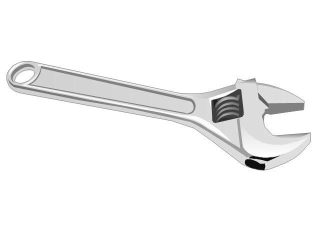
Adjustable spanner
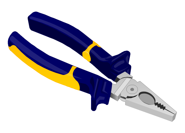
Lineman's pliers
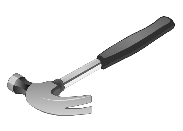
Claw hammer
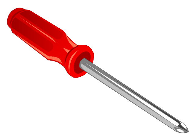
Phillips screwdriver
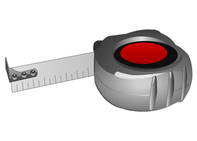
Self-retracting tape measure
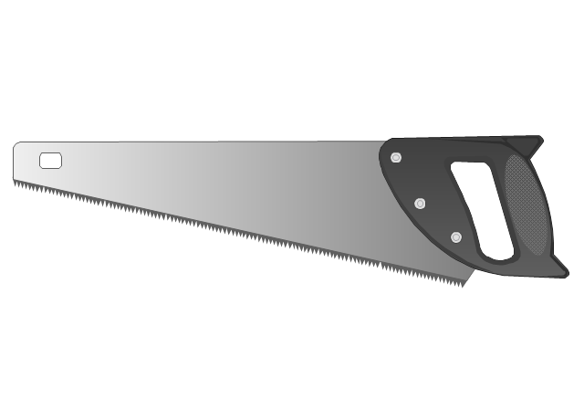
Crosscut hand saw
Nail

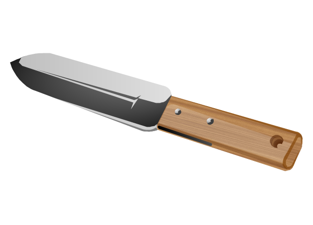
Hori-Hori garden knife
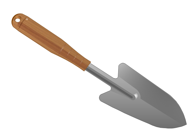
Gardening trowel
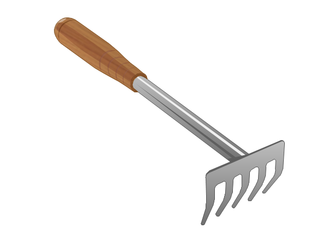
Garden rake
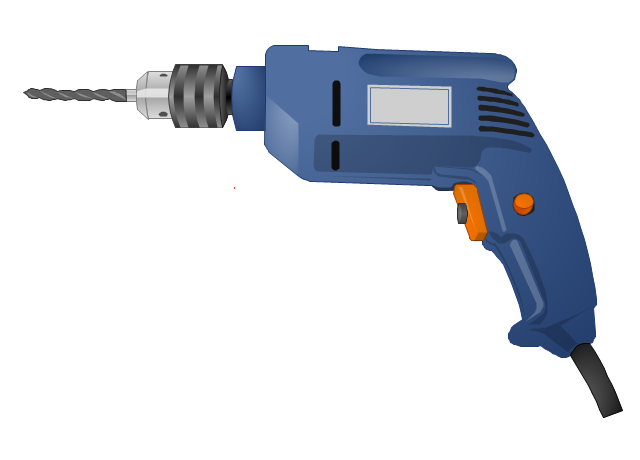
Pistol-grip electric drill
- Circuits and Logic Diagram Software | Example Of Pneumatic And ...
- Design elements - Fluid power equipment | Valves - Vector stencils ...
- Mechanical Drawing Symbols | Design elements - Pneumatic pumps ...
- Design elements - Pneumatic pumps and motors | Mechanical ...
- Pneumatics Symbol Equipments
- Pneumatic 5-ported 3-position valve template - Mac | Design ...
- Design elements - Pneumatic pumps and motors | Design elements ...
- Design elements - Pneumatic pumps and motors | Fluid power ...
- Design elements - Fluid power equipment | Design elements ...
- Mechanical Drawing Symbols | Design elements - Pneumatic pumps ...
- Hydraulics
- Hydraulic And Pneumatic Systems Examples
- Pneumatic 5-ported 3-position valve template - Mac | Mechanical ...
- Design elements - Fluid power equipment
- Design elements - Pneumatic pumps and motors | Pneumatic pumps ...
- Design elements - Pneumatic pumps and motors | Design elements ...
- Hydraulic schematic | Directional control valve | Directional control ...
- Fluid power equipment - Vector stencils library | Hydraulic 4-ported 3 ...
- Air Flow Equipment Symbol In Pneumatic System
- Schematic Pneumatic Mechanical Valve