HelpDesk
How to Draw a Chemical Process Flow Diagram

Business Process Elements: Activities
")

Diagramming Software for Business Process
")
HelpDesk
How to Draw a Process Flow Diagram in ConceptDraw PRO

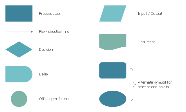
The vector stencils library "Process flowchart" contains 9 flow chart symbols.
Use it to design your process flowcharts with ConceptDraw PRO diagramming and vector drawing software.
"A flowchart is a type of diagram that represents an algorithm, workflow or process, showing the steps as boxes of various kinds, and their order by connecting them with arrows. ...
Kaoru Ishikawa defined the flowchart as one of the seven basic tools of quality control, next to the histogram, Pareto chart, check sheet, control chart, cause-and-effect diagram, and the scatter diagram. ...
Common alternative names include: flowchart, process flowchart, functional flowchart, process map, process chart, functional process chart, business process model, process model, process flow diagram, work flow diagram, business flow diagram. The terms "flowchart" and "flow chart" are used interchangeably." [Flowchart. Wikipedia]
The example of flow chart symbols "Design elements - Process flowchart" is included in the Seven Basic Tools of Quality solution from the Quality area of ConceptDraw Solution Park.
Process flowchart symbols
- Process Flowchart | Process Flow Diagram | Types of Flowcharts ...
- Process Flow Diagram Symbols | Design elements - Chemical ...
- Basic Flowchart Symbols and Meaning | Process Flowchart ...
- Process Flowchart | Process Flow Diagram Symbols | Design ...
- Flowchart Symbols Or Design Elements
- Process Flow Diagram Symbols | Process Flowchart | Chemical and ...
- Swim Lane Flowchart Symbols | Cross-Functional Flowchart (Swim ...
- Process Flow Diagram Symbols | Chemical and Process ...
- Chemical Engineering | Process Flow Diagram Symbols | Design ...
- Process Flow Diagram Symbols | Design elements - Industrial ...
- Process Flow Diagram | Design elements - Heating equipment ...
- Design Procedure Flow Chart In Design Of Mechanical Element
- Process Flow Diagram Symbols | Design elements - Valves and ...
- Process Flowchart | How to Draw a Chemical Process Flow Diagram ...
- Basic Flowchart Symbols and Meaning | Design elements ...
- Design elements - Industrial equipment | Process Flow Diagram ...
- Process Flow Diagram | Design elements - Fluid power valves ...
- Process Engineering | Process Flow Diagram Symbols | Design ...
- Process Flow Diagram Symbols | Design elements - Vessels ...
- How to Draw a Chemical Process Flow Diagram