"The symbols and conventions used in welding documentation are specified in national and international standards such as ISO 2553 Welded, brazed and soldered joints -- Symbolic representation on drawings and ISO 4063 Welding and allied processes -- Nomenclature of processes and reference numbers. The US standard symbols are outlined by the American National Standards Institute and the American Welding Society and are noted as "ANSI/ AWS".
In engineering drawings, each weld is conventionally identified by an arrow which points to the joint to be welded. The arrow is annotated with letters, numbers and symbols which indicate the exact specification of the weld. In complex applications, such as those involving alloys other than mild steel, more information may be called for than can comfortably be indicated using the symbols alone. Annotations are used in these cases." [Symbols and conventions used in welding documentation. Wikipedia]
The example chart "Elements of welding symbol" is redesigned using the ConceptDraw PRO diagramming and vector drawing software from the Wikipedia file: Elements of a welding symbol.PNG.
[en.wikipedia.org/ wiki/ File:Elements_ of_ a_ welding_ symbol.PNG]
The diagram example "Elements location of a welding symbol" is contained in the Mechanical Engineering solution from the Engineering area of ConceptDraw Solution Park.
Welding joint symbol chart

IDEF9 Standard

 Mechanical Engineering
This solution extends ConceptDraw PRO v.9 mechanical drawing software (or later) with samples of mechanical drawing symbols, templates and libraries of design elements, for help when drafting mechanical engineering drawings, or parts, assembly, pneumatic,
The vector stencils library "Education charts" contains 12 graphs and charts: area chart, column chart, divided bar diagram, histogram, horizontal bar graph, line graph, pie chart, ring chart, scatter plot.
Use it to create your education infogram in the ConceptDraw PRO diagramming and vector drawing software.
The vector stencils library "Education charts" is included in the Education Infographics solution from the Business Infographics area of ConceptDraw Solution Park.
Use it to create your education infogram in the ConceptDraw PRO diagramming and vector drawing software.
The vector stencils library "Education charts" is included in the Education Infographics solution from the Business Infographics area of ConceptDraw Solution Park.
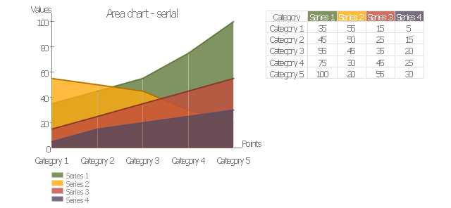
Area chart - serial
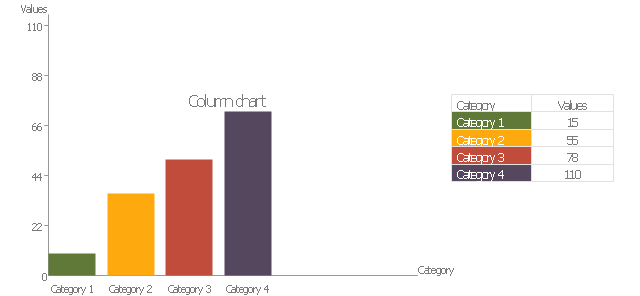
Column chart
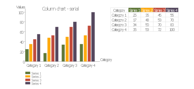
Column chart - serial
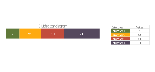
Divided bar diagram
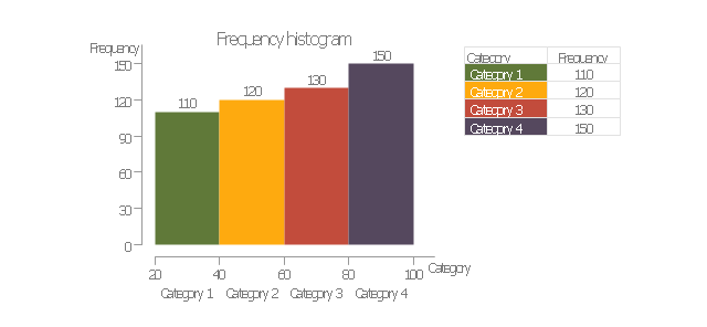
Frequency histogram
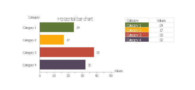
Horizontal bar chart
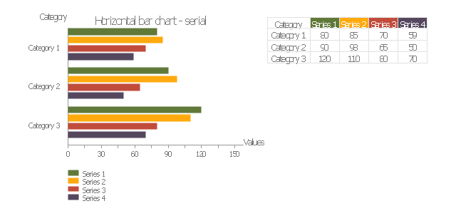
Horizontal bar chart - serial
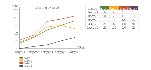
Line chart - serial
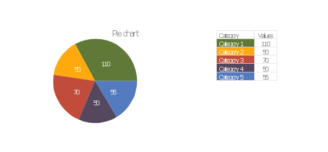
Pie chart
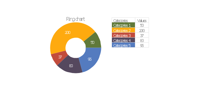
Ring chart
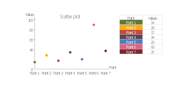
Scatter plot
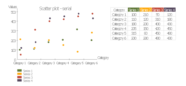
Scatter plot - serial
- Types of Welding in Flowchart | Technical Drawing Software ...
- Types of Welding in Flowchart | Technical Drawing Software ...
- Sample Of Flow Process Chart On Shop Welding
- Operation Process Chart For Welding Shope
- Types of Flowcharts | Types of Flowchart - Overview | Basic ...
- Welding Process Chart Format
- Weld Type Flow Chart
- Mechanical Drawing Symbols | Welding symbols | Process ...
- Different Types Of Welding Process Chart
- Welding Process Flow Diagram Software
- Types Welding Process With Flow Chart
- Process Flow Chart Of Welding
- How To Make Operation Process Chart For Welding Shop
- Types of Welding in Flowchart | Business Process Mapping — How ...
- Types of Welding in Flowchart | Entity Relationship Diagram ...
- Draw A Flow Chart Of The Main Component Of The State Government
- Types of Welding in Flowchart | Elements location of a welding ...
- Welding Types Flow Chart
- Types of Welding in Flowchart | Examples of Flowcharts, Org Charts ...
- Types of Welding in Flowchart | Welding And Fabrication Flow ...