This is a schematic process flow diagram of the processes used in a typical oil refinery.
This process flow diagram (PFD) example was redesigned from the Wikimedia Commons file: RefineryFlow.png. [commons.wikimedia.org/ wiki/ File:RefineryFlow.png]
This file is licensed under the Creative Commons Attribution-Share Alike 3.0 Unported license. [creativecommons.org/ licenses/ by-sa/ 3.0/ deed.en]
"An oil refinery or petroleum refinery is an industrial process plant where crude oil is processed and refined into more useful products such as petroleum naphtha, gasoline, diesel fuel, asphalt base, heating oil, kerosene and liquefied petroleum gas. Oil refineries are typically large, sprawling industrial complexes with extensive piping running throughout, carrying streams of fluids between large chemical processing units. In many ways, oil refineries use much of the technology of, and can be thought of, as types of chemical plants. The crude oil feedstock has typically been processed by an oil production plant. There is usually an oil depot (tank farm) at or near an oil refinery for the storage of incoming crude oil feedstock as well as bulk liquid products.
An oil refinery is considered an essential part of the downstream side of the petroleum industry." [Oil refinery. Wikipedia]
The PFD example "Process flow diagram - Typical oil refinery" was created using the ConceptDraw PRO diagramming and vector drawing software extended with the Chemical and Process Engineering solution from the Chemical and Process Engineering area of ConceptDraw Solution Park.
Process Flow Diagram (PFD)
-process-flow-diagram---typical-oil-refinery.png--diagram-flowchart-example.png)
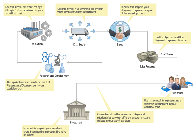
"Workflow components.
A workflow can usually be described using formal or informal flow diagramming techniques, showing directed flows between processing steps. Single processing steps or components of a workflow can basically be defined by three parameters:
(1) input description: the information, material and energy required to complete the step,
(2) transformation rules, algorithms, which may be carried out by associated human roles or machines, or a combination,
(3) output description: the information, material and energy produced by the step and provided as input to downstream steps.
Components can only be plugged together if the output of one previous (set of) component(s) is equal to the mandatory input requirements of the following component. Thus, the essential description of a component actually comprises only in- and output that are described fully in terms of data types and their meaning (semantics). The algorithms' or rules' description need only be included when there are several alternative ways to transform one type of input into one type of output – possibly with different accuracy, speed, etc.
When the components are non-local services that are invoked remotely via a computer network, such as Web services, additional descriptors (such as QoS and availability) also must be considered." [Workflow. Wikipedia]
The workflow diagram template for the ConceptDraw PRO diagramming and vector drawing software is included in the Workflow Diagrams solution from the Business Processes area of ConceptDraw Solution Park.
Workflow diagram template
- Process flow diagram - Typical oil refinery | Crude oil distillation unit ...
- Crude oil distillation unit - PFD | Natural gas condensate - PFD ...
- Oil And Gas Production Process Flow Diagram
- Process Flow Diagram Symbols
- Process flow diagram - Typical oil refinery | Amine treating unit ...
- Process flow diagram - Typical oil refinery | Process Flowchart ...
- Process Flow Diagram Symbols | Process flow diagram - Typical oil ...
- Process flow diagram - Typical oil refinery | Chemical and Process ...
- Onion Diagram Process Design | Process flow diagram - Typical oil ...
- Crude oil distillation unit - PFD | Process Flow Diagram Symbols ...
- Process Flow Diagram Symbols | Process Flowchart | Chemical and ...
- Process flow diagram - Typical oil refinery
- Process Flow Diagram Symbols | Chemical Engineering | Process ...
- Cause and effect diagram - Increase in productivity | Process ...
- Process Flow Chart | Process Flow Diagram | Types of Flowcharts ...
- Process Flowchart | Process Flow Diagram Symbols | Process flow ...
- Diagram Of A Gas Flow
- Piping and Instrumentation Diagram Software | Process flow ...
- Amine treating unit schematic diagram | Process flow diagram (PFD ...
- Process Flow Diagram Symbols | Technical Drawing Software ...