Standard Universal Audio & Video Connection Types
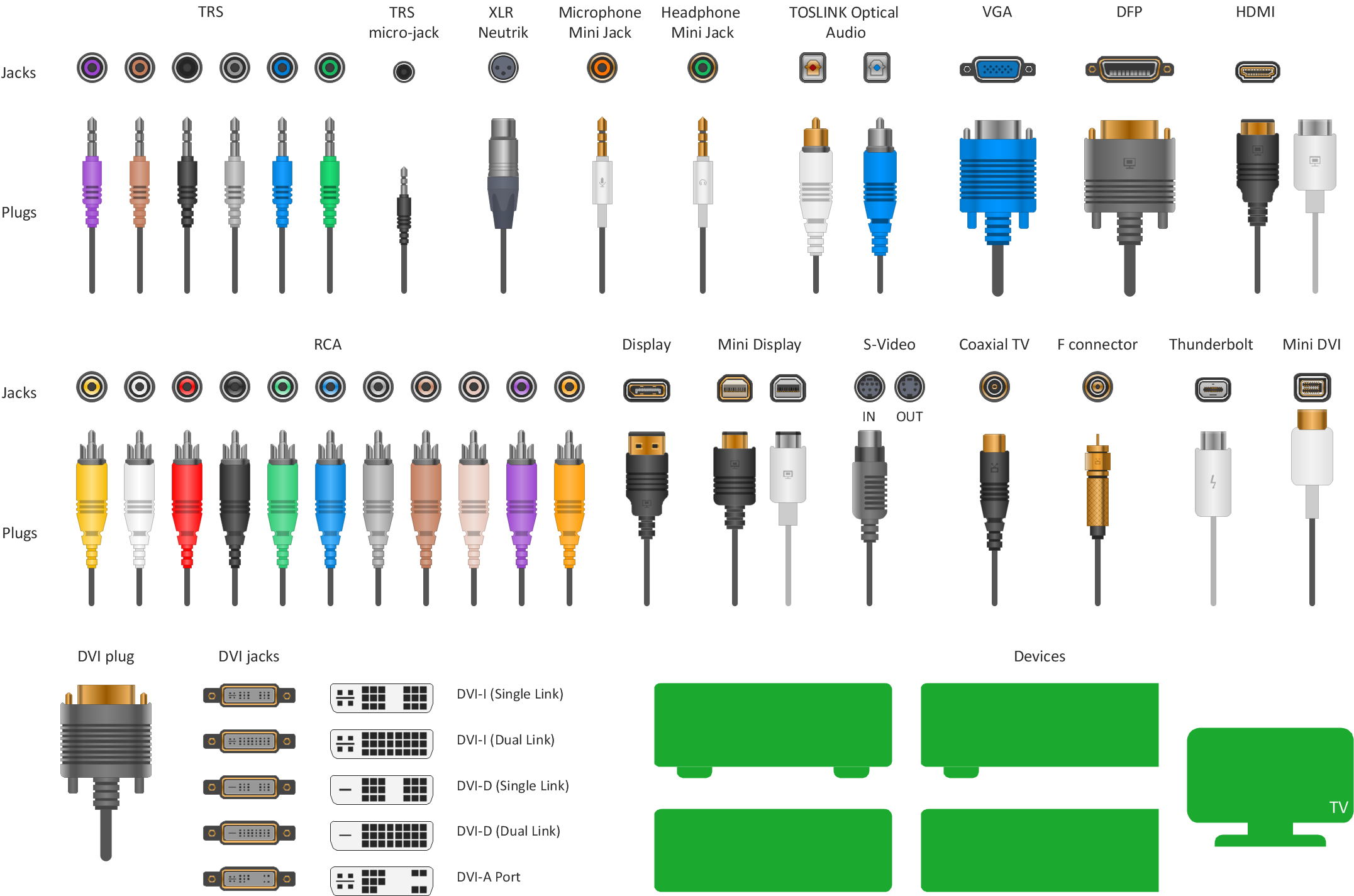
The vector stencils library "Audio and video connectors" contains 94 symbols of audio and video connectors (TRS, TS, XLR, microphone, headphone, TOSLINK, DVI, VGA, DFP, S-Video, RCA, display port, HDMI, Thunderbolt, coaxial TV, F connector, MIDI) and device silhouettes.
Use these jacks and plugs clipart icons for drawing hook up diagrams.
"Audio connectors and video connectors are electrical connectors (or optical connectors) for carrying audio signal and video signal, of either analog or digital format. Analog A/ V connectors often use shielded cables to inhibit radio frequency interference (RFI) and noise." [Audio and video connector. Wikipedia]
"The existence of many different audio and video standards necessitates the definition of hardware interfaces, which define the physical characteristics of the connections between electrical equipment. This includes the types and numbers of wires required along with the strength and frequency of the signal. It also includes the physical design of the plugs and sockets.
An interface may define a connector that is used only by that interface (e.g., DVI) or may define a connector that is also used by another interface; for example, RCA connectors are defined both by the composite video and component video interfaces.
Audio connectors and video connectors are electrical connectors (or optical connectors) for carrying audio signal and video signal, of either analog or digital format. Analog A/ V connectors often use shielded cables to inhibit radio frequency interference (RFI) and noise.
Since both analog and digital signals are used with some styles of connectors, knowledge of the interface used is necessary for a successful transfer of signals. Some interface types use only a distinctive connector or family of connectors, to ensure compatibility. Especially with analog interfaces, physically interchangeable connectors may not carry compatible signals.
Some of these connectors, and other types of connectors, are also used at radio frequency (RF) to connect a radio or television receiver to an antenna or to a cable system..." [Audio and video interfaces and connectors. Wikipedia]
The clipart icons example "Design elements - Audio and video connectors" was created using the ConceptDraw PRO diagramming and vector drawing software extended with the Audio and Video Connectors solution from the Engineering area of ConceptDraw Solution Park.
Audio and video jacks and plugs

ConceptDraw Arrows10 Technology

Electric Visual

Electrical Symbols, Electrical Diagram Symbols

ConceptDraw DIAGRAM Comparison with Omnigraffle Professional and MS Visio

- Standard Universal Audio & Video Connection Types | Network ...
- Audio and video connectors - Vector stencils library | Standard ...
- DVI connector types
- DVI connector types | Design elements - Audio and video ...
- Standard Universal Audio & Video Connection Types | Design ...
- DVI connector types | Standard Universal Audio & Video Connection ...
- Audio Visual Connectors Types | How to Make Audio and Video ...
- DVI connector types | Types Of Computer Plugs
- DVI pinout diagram | Standard Universal Audio & Video Connection ...
- Standard Universal Audio & Video Connection Types | Audio Visual ...
- Design elements - Audio and video connectors
- DVI pinout diagram | DVI connector types | Audio and Video ...
- Standard Universal Audio & Video Connection Types | Audio and ...
- Connector Types Computers
- Audio Visual Cables and Connectors | Audio Visual Connectors ...
- Audio Visual Connectors Types | Basic Flowchart Symbols and ...
- VGA connector pinout | Standard Types of Universal Audio & Video ...
- Audio & Video Connector Types | DVI connector types | Audio and ...
- Audio Visual Connectors Types | Standard Universal Audio & Video ...