"Dimensions of service quality.
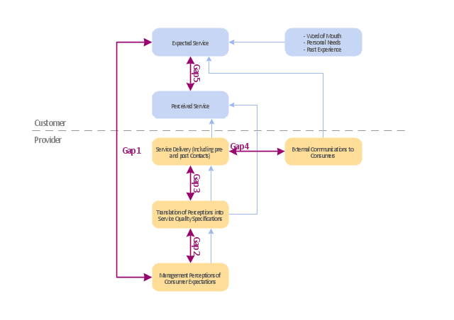
A customer's expectation of a particular service is determined by factors such as recommendations, personal needs and past experiences. The expected service and the perceived service sometimes may not be equal, thus leaving a gap. The service quality model or the ‘GAP model’ developed by a group of authors- Parasuraman, Zeithaml and Berry at Texas and North Carolina in 1985 , highlights the main requirements for delivering high service quality. It identifies five ‘gaps’ that cause unsuccessful delivery. Customers generally have a tendency to compare the service they 'experience' with the service they 'expect' . If the experience does not match the expectation , there arises a gap. Ten determinants that may influence the appearance of a gap were described by Parasuraman, Zeithaml and Berry. in the SERVQUAL model: reliability, responsiveness, competence, access, courtesy, communication, credibility, security, understanding the customer and tangibles.
Later, the determinants were reduced to five: tangibles; reliability; responsiveness; service assurance and empathy in the so called RATER model." [Service quality. Wikipedia]
The block diagram example "Gap model of service quality" was created using the ConceptDraw PRO diagramming and vector drawing software extended with the Block Diagrams solution from the area "What is a Diagram" of ConceptDraw Solution Park.
Block diagram
 Mathematics
Mathematics solution extends ConceptDraw PRO software with templates, samples and libraries of vector stencils for drawing the mathematical illustrations, diagrams and charts.
"Logical topology, or signal topology, is the arrangement of devices on a computer network and how they communicate with one another. How devices are connected to the network through the actual cables that transmit data, or the physical structure of the network, is called the physical topology. Physical topology defines how the systems are physically connected. It represents the physical layout of the devices on the network. The logical topology defines how the systems communicate across the physical topologies.
Logical topologies are bound to network protocols and describe how data is moved across the network. ...
EXAMPLE : twisted pair Ethernet is a logical bus topology in a physical star topology layout. while IBM's token ring is a logical ring topology, it is physically set up in star topology." [Logical topology. Wikipedia]
This Cisco logical computer network diagram example was created using the ConceptDraw PRO diagramming and vector drawing software extended with the Cisco Network Diagrams solution from the Computer and Networks area of ConceptDraw Solution Park.
Logical network topology diagram

- Software For Making Bus Route Diagrammatic Maps
- Diagrammatic Representation Of Interrelationship Of Metabolic ...
- Which Is Diagrammatic Representation Illustrating The Solution To A
- Diagrammatic Representation Of Data Line Graph Bar Diagram Pie
- Diagrammatic Representation Of Water Cycle
- A Diagrammatic Representation Of The Accounting System
- A Flowchart Is A Diagrammatic Representation Of The Plan Of
- Is A Diagrammatic Representation Illustrates A Solution To A Given
- Aerospace and Transport | Diagrammatic Representation Of A ...
- Process Flowchart | Cross-Functional Flowchart | Diagrammatic ...
- Diagrammatic Representation Of A Bus Topology Showing All
- Diagrammatic Representation Of Major Components Of Crude ...
- Process Flowchart | Cross-Functional Flowchart | Diagrammatic ...
- Diagrammatic Illustration Of Organizational Structure Of A University
- Flow chart Example. Warehouse Flowchart | Diagrammatic ...
- Diagrammatic Illustration Of The Glycolytic Pathway
- Flowchart Software | How to Build a Flowchart | Flowcharting ...
- Diagrammatic Illustration On How Information Is Processed
- Diagrammatic Representation Of Information Resource ...