The vector stencils library "UML component diagrams" contains 36 symbols for the ConceptDraw PRO diagramming and vector drawing software.
"In the Unified Modeling Language, a component diagram depicts how components are wired together to form larger components and or software systems. They are used to illustrate the structure of arbitrarily complex systems. ...
Symbols.
This may have a visual stereotype in the top right of the rectangle of a small rectangle with two even smaller rectangles jutting out on the left.
The lollipop, a small circle on a stick represents an implemented or provided interface. The socket symbol is a semicircle on a stick that can fit around the lollipop. This socket is a dependency or needed interface." [Component diagram. Wikipedia]
The example "Design elements - UML component diagrams" is included in the Rapid UML solution from the Software Development area of ConceptDraw Solution Park.
UML component diagram symbols

The vector stencils library "IDEF0 diagrams" contains 18 symbols for drawing IDEF0 function modeling diagrams using the ConceptDraw PRO diagramming and vector drawing software.
"The IDEF0 model ... is based on a simple syntax. Each activity is described by a verb-based label placed in a box. Inputs are shown as arrows entering the left side of the activity box while output are shown as exiting arrows on the right side of the box. Controls are displayed as arrows entering the top of the box and mechanisms are displayed as arrows entering from the bottom of the box. Inputs, Controls, Outputs, and Mechanisms are all referred to as concepts.
- Arrow : A directed line, composed of one or more arrow segments, that models an open channel or conduit conveying data or objects from source (no arrowhead) to use (with arrowhead). There are 4 arrow classes: Input Arrow, Output Arrow, Control Arrow, and Mechanism Arrow (includes Call Arrow). See Arrow Segment, Boundary Arrow, Internal Arrow.
- Box : A rectangle, containing a name and number, used to represent a function.
- Context : The immediate environment in which a function (or set of functions on a diagram) operates.
- Decomposition : The partitioning of a modeled function into its component functions.
- Fork : The junction at which an IDEF0 arrow segment (going from source to use) divides into two or more arrow segments. May denote unbundling of meaning.
- Function : An activity, process, or transformation (modeled by an IDEF0 box) identified by a verb or verb phrase that describes what must be accomplished.
- Join : The junction at which an IDEF0 arrow segment (going from source to use) merges with one or more other arrow segments to form a single arrow segment. May denote bundling of arrow segment meanings.
- Node : A box from which child boxes originate; a parent box. See Node Index, Node Tree, Node Number, Node Reference, Diagram Node Number." [IDEF0. Wikipedia]
The example "Design elements - IDEF0 diagram" is included in the IDEF0 Diagrams solution from the Software Development area of ConceptDraw Solution Park.
IDEF0 symbols

"RT-middleware (Robotics Technology Middleware) is a common platform standards for Robots based on the distributed object technology. RT-middleware supports the construction of various networked robotic systems by the integration of various network enabled robotic elements called RT-Components. The specification standard of the RT-component is discussed / defined by the Object Management Group (OMG). ...
In the RT-middleware, robotics elements, such as actuators, are regarded as RT-components, and the whole robotic system is constructed by connecting those RT-components. This distributed architecture helps developers to re-use the robotic elements, and boosts the reliability of the robotic system.
Each RT-component has port as an endpoint for communicating other RT-components. Every port has its type and the ports which have the same type can be connected each other.
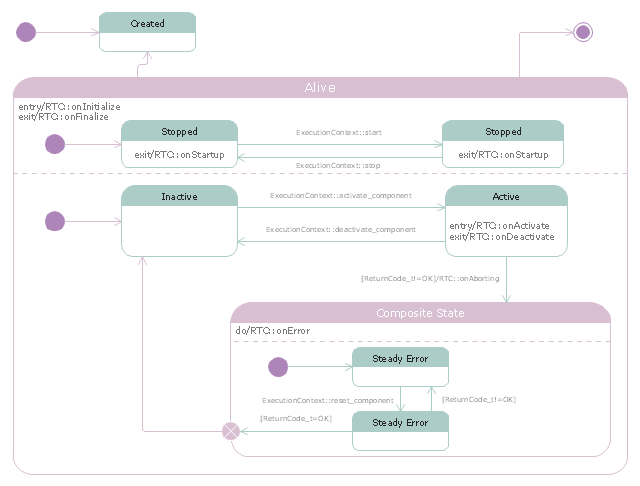
RT-components also has its state, so the RT-components behaves as state machines. The states that RT-components can have are CREATED, INACTIVE, ACTIVE, and ERROR, and the states and behaviors are controlled by the execution-context. If developers want to change the behavior of their RT-components, the execution-context can be replaced at run-time." [RT middleware. Wikipedia]
The UML state machine diagram example "State transitions of RT-component" was created using the ConceptDraw PRO diagramming and vector drawing software extended with the Rapid UML solution from the Software Development area of ConceptDraw Solution Park.
In the RT-middleware, robotics elements, such as actuators, are regarded as RT-components, and the whole robotic system is constructed by connecting those RT-components. This distributed architecture helps developers to re-use the robotic elements, and boosts the reliability of the robotic system.
Each RT-component has port as an endpoint for communicating other RT-components. Every port has its type and the ports which have the same type can be connected each other.
RT-components also has its state, so the RT-components behaves as state machines. The states that RT-components can have are CREATED, INACTIVE, ACTIVE, and ERROR, and the states and behaviors are controlled by the execution-context. If developers want to change the behavior of their RT-components, the execution-context can be replaced at run-time." [RT middleware. Wikipedia]
The UML state machine diagram example "State transitions of RT-component" was created using the ConceptDraw PRO diagramming and vector drawing software extended with the Rapid UML solution from the Software Development area of ConceptDraw Solution Park.
UML state machine diagram
- Illustration | UML Component Diagram . Design Elements ...
- UML Component Diagram | Diagramming Software for Design UML ...
- Design elements - Rapid UML solution ( component diagram ...
- UML Deployment Diagram
- UML Component Diagram - Conceptdraw.com
- How to create a UML Diagram | UML Component Diagram . Design ...
- UML Activity Diagram | UML Activity Diagram . Design Elements
- UML Activity Diagram , Design Elements | UML Use Case Diagram ...
- UML Deployment Diagram | Diagramming Software for Design UML ...
- UML Block Diagram | Diagramming Software for Design UML ...
- UML Component Diagram
- UML Object Diagram . Design Elements
- UML Deployment Diagram
- UML Deployment Diagram | Diagramming Software for Design UML ...
- UML Component Diagram - Conceptdraw.com
- Engineering | Diagramming Software for Design UML Component ...
- UML Component Diagram . Design Elements | Software and ...
- Diagramming Software for Design UML Component Diagrams | UML ...
- Diagramming Software for Design UML Component Diagrams | UML ...
- Timing diagram | UML Timing Diagram , Design Elements ...