The vector stencils library "UML state machine diagrams" contains 35 symbols for the ConceptDraw PRO diagramming and vector drawing software.
"The state diagram in the Unified Modeling Language is essentially a Harel statechart with standardized notation, which can describe many systems, from computer programs to business processes. In UML 2 the name has been changed to State Machine Diagram. The following are the basic notational elements that can be used to make up a diagram:
(1) Filled circle, pointing to the initial state.
(2) Hollow circle containing a smaller filled circle, indicating the final state (if any).
(3) Rounded rectangle, denoting a state. Top of the rectangle contains a name of the state. Can contain a horizontal line in the middle, below which the activities that are done in that state are indicated.
(4) Arrow, denoting transition. The name of the event (if any) causing this transition labels the arrow body. A guard expression may be added before a "/ " and enclosed in square-brackets ( eventName[guardExpression] ), denoting that this expression must be true for the transition to take place. If an action is performed during this transition, it is added to the label following a "/ " ( eventName[guardExpression]/ action ).
(5) Thick horizontal line with either x>1 lines entering and 1 line leaving or 1 line entering and x>1 lines leaving. These denote join/ fork, respectively." [State diagram (UML). Wikipedia]
The example "Design elements - UML state machine diagrams" is included in the Rapid UML solution from the Software Development area of ConceptDraw Solution Park.
UML state machine diagram symbols

The vector stencils library "Machines and equipment" contains 24 symbols of industrial machines and equipment.
Use the design elements library "Machines and equipment" for drawing plant interior design plans, manufacturing equipment layouts and factory floor plans using the ConceptDraw PRO diagramming and vector drawing software.
"Manufacturing is the production of goods for use or sale using labor and machines, tools, chemical and biological processing, or formulation. The term may refer to a range of human activity, from handicraft to high tech, but is most commonly applied to industrial production, in which raw materials are transformed into finished goods on a large scale.
Modern manufacturing includes all intermediate processes required for the production and integration of a product's components. Some industries, such as semiconductor and steel manufacturers use the term fabrication instead.
The manufacturing sector is closely connected with engineering and industrial design." [Manufacturing. Wikipedia]
The shapes library "Machines and equipment" is included in the Plant Layout Plans solution from the Building Plans area of ConceptDraw Solution Park.
Machines and equipment symbols

The vector stencils library "Bank UML state machine diagram" contains 21 shapes for drawing UML state machine diagrams.
Use it for object-oriented modeling of your bank information system.
"The state diagram in the Unified Modeling Language is essentially a Harel statechart with standardized notation, which can describe many systems, from computer programs to business processes. In UML 2 the name has been changed to State Machine Diagram. The following are the basic notational elements that can be used to make up a diagram:
* Filled circle, pointing to the initial state.
* Hollow circle containing a smaller filled circle, indicating the final state (if any).
* Rounded rectangle, denoting a state. Top of the rectangle contains a name of the state. Can contain a horizontal line in the middle, below which the activities that are done in that state are indicated.
* Arrow, denoting transition. The name of the event (if any) causing this transition labels the arrow body. A guard expression may be added before a "/ " and enclosed in square-brackets ( eventName[guardExpression] ), denoting that this expression must be true for the transition to take place. If an action is performed during this transition, it is added to the label following a "/ " ( eventName[guardExpression]/ action ).
* Thick horizontal line with either x>1 lines entering and 1 line leaving or 1 line entering and x>1 lines leaving. These denote join/ fork, respectively." [State machine diagram. Wikipedia]
This example of UML state machine diagram symbols for the ConceptDraw PRO diagramming and vector drawing software is included in the ATM UML Diagrams solution from the Software Development area of ConceptDraw Solution Park.
UML state machine diagram symbols

"State machine diagram is a behavior diagram which shows discrete behavior of a part of designed system through finite state transitions. State machine diagrams can also be used to express the usage protocol of part of a system. Two kinds of state machines defined in UML 2.4 are:
(1) behavioral state machine, and
(2) protocol state machine.
The following nodes and edges are typically drawn in state machine diagram: behavioral state, behavioral transition, protocol state, protocol transition, different pseudostates. ...
Behavioral state machine is specialization of behavior and is used to specify discrete behavior of a part of designed system through finite state transitions. The state machine formalism used in this case is an object-based variant of Harel statecharts.
Behavior is modeled as a traversal of a graph of state nodes connected with transitions. Transitions are triggered by the dispatching of series of events. During the traversal, the state machine could also execute some activities. ...
Protocol state machine is a specialization of behavioral state machine and is used to express usage protocol or lifecycle of a classifier. It specifies which operations of the classifier can be called in which state and under which condition, thus specifying the allowed call sequences on the classifier’s operations. Protocol state machines express the legal transitions that a classifier can trigger." [uml-diagrams.org/ state-machine-diagrams.html]
The template "UML state machine diagram" for the ConceptDraw PRO diagramming and vector drawing software is included in the Rapid UML solution from the Software Development area of ConceptDraw Solution Park.
www.conceptdraw.com/ solution-park/ software-uml
UML state machine diagram

The vector stencils library "Fluid power equipment" contains 113 symbols of hydraulic and pneumatic equipment including pumps, motors, air compressors, cylinders, meters, gauges, and actuators. Use it to design fluid power and hydraulic control systems.
"Fluid power is the use of fluids under pressure to generate, control, and transmit power. Fluid power is subdivided into hydraulics using a liquid such as mineral oil or water, and pneumatics using a gas such as air or other gases. Compressed-air and water-pressure systems were once used to transmit power from a central source to industrial users over extended geographic areas; fluid power systems today are usually within a single building or mobile machine." [Fluid power. Wikipedia]
The shapes example "Design elements - Fluid power equipment" was created using the ConceptDraw PRO diagramming and vector drawing software extended with the Mechanical Engineering solution from the Engineering area of ConceptDraw Solution Park.
Fluid power symbols

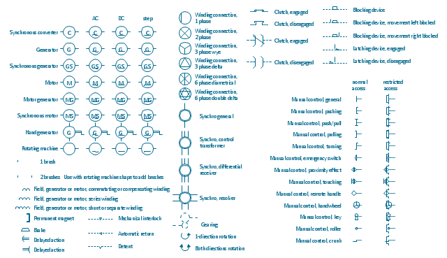
The vector stencils lybrary "Rotating equipment" contains 55 symbols of rotating equipment: converters, generators, motors, rotating machines, and their parts and labels.
Use to design systems containing rotating electrical equipment (i.e., motors), armatures, brushes, and related mechanical devices ( brakes, gearing, clutches, interlocks).
"The academic study of electric machines is the universal study of electric motors and electric generators. By the classic definition, electric machine is synonymous with electric motor or electric generator, all of which are electromechanical energy converters: converting electricity to mechanical power (i.e., electric motor) or mechanical power to electricity (i.e., electric generator). The movement involved in the mechanical power can be rotating or linear.
Although transformers do not contain any moving parts they are also included in the family of electric machines because they utilise electromagnetic phenomena.
Electric machines (i.e., electric motors) consume approximately 60% of all electricity produced. Electric machines (i.e., electric generators) produce virtually all electricity consumed. Electric machines have become so ubiquitous that they are virtually overlooked as an integral component of the entire electricity infrastructure. Developing ever more efficient electric machine technology and influencing their use are crucial to any global conservation, green energy, or alternative energy strategy." [Electric machine. Wikipedia]
The shapes example "Design elements - Rotating equipment" was drawn using the ConceptDraw PRO diagramming and vector drawing software extended with the Electrical Engineering solution from the Engineering area of ConceptDraw Solution Park.
Rotating equipment symbols
- Symbols Of Machine Components
- Interior Design Machines and Equipment - Design Elements | Basic ...
- Basic Flowchart Symbols and Meaning | Interior Design Machines ...
- Basic Flowchart Symbols and Meaning | UML Flowchart Symbols ...
- Geometric Symbols Of Machine Design
- Basic Flowchart Symbols and Meaning | Process Flowchart ...
- Process Flowchart | Basic Flowchart Symbols and Meaning ...
- Technical drawing - Machine parts assembling | Process Flowchart ...
- Basic Flowchart Symbols and Meaning | Process Flowchart ...
- Symbols Of Machine Drawing
- Mechanical Drawing Symbols | UML Flowchart Symbols | Basic ...
- Fire safety equipment - Vector stencils library | Basic Flowchart ...
- Mechanical Drawing Symbols | Technical drawing - Machine parts ...
- Symbol Used For Machine Element
- Mechanical Drawing Symbols | Interior Design Machines and ...
- Symbol Of Rotating Machine
- Symbols In Machine Design
- Machine System Design Symbol
- Design elements - Machines and equipment | Cnc Drawing Symbol
- Design elements - Industrial equipment | Process Flowchart ...