 Fire and Emergency Plans
This solution extends ConceptDraw software with samples, templates and design elements for drawing the Fire and Emergency Plans.
Use this template to develop the home layouts, space plans, interior design, kitchen and bathroom design, architectural and construction documents using ConceptDraw PRO diagramming and vector drawing software.
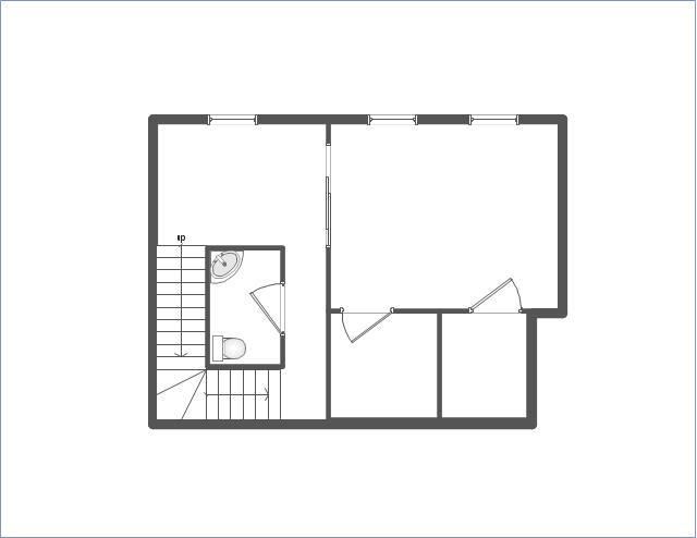
"A floor plan is the most fundamental architectural diagram, a view from above showing the arrangement of spaces in building in the same way as a map, but showing the arrangement at a particular level of a building. Technically it is a horizontal section cut through a building (conventionally at three feet / one metre above floor level), showing walls, windows and door openings and other features at that level. The plan view includes anything that could be seen below that level: the floor, stairs (but only up to the plan level), fittings and sometimes furniture. Objects above the plan level (e.g. beams overhead) can be indicated as dotted lines." [Architectural drawing. Wikipedia]
The Home floor plan template is included in the Floor Plans solution from the Building Plans area of ConceptDraw Solution Park.
www.conceptdraw.com/ solution-park/ floor-plans
 Physics
Physics solution extends ConceptDraw PRO software with templates, samples and libraries of vector stencils for drawing the physical illustrations, diagrams and charts.
This cafe electrical floor plan sample shows the outlet and switch layout.
"An electrical drawing, is a type of technical drawing that shows information about power, lighting, and communication for an engineering or architectural project. Any electrical working drawing consists of "lines, symbols, dimensions, and notations to accurately convey an engineering's design to the workers, who install the electrical system on the job".
A complete set of working drawings for the average electrical system in large projects usually consists of:
(1) A plot plan showing the building's location and outside electrical wiring.
(2) Floor plans showing the location of electrical systems on every floor.
(3) Power-riser diagrams showing panel boards.
(4) Control wiring diagrams.
(5) Schedules and other information in combination with construction drawings.
Electrical drafters prepare wiring and layout diagrams used by workers who erect, install, and repair electrical equipment and wiring in communication centers, power plants, electrical distribution systems, and buildings." [Electrical drawing. Wikipedia]
The outlet and switch layout example "Cafe electrical floor plan" was created using the ConceptDraw PRO diagramming and vector drawing software extended with the Electric and Telecom Plans solution from the Building Plans area of ConceptDraw Solution Park.
Outlet and switch layout

- Diagramming Software for Design UML Object Diagrams ...
- CAD Drawing Software for Making Mechanic Diagram and Electrical ...
- Door Symbol In Architecture Blueprint
- Network Diagramming Software for Design Basic Network Diagrams ...
- Door Openings Plan Section Drawing
- Landscape Architecture with ConceptDraw PRO | Emergency Exit ...
- Landscape Architecture with ConceptDraw PRO | Gym Floor Plan ...
- Blueprint Software | Network Architecture | Interior Design Office ...
- Landscape Architecture with ConceptDraw PRO | Free Construction ...
- Architectural Symbols Door And Windows
- ConceptDraw PRO Network Diagram Tool | Design elements ...
- Electrical Diagram Symbols | Electrical Drawing Software | How To ...
- Room planning with ConceptDraw PRO | Landscape Architecture ...
- Security and Access Plans | How to Draw a Security and Access ...
- Building Drawing Software for Design Office Layout Plan | CAD ...
- CAD Drawing Software for Architectural Designs
- How To use House Electrical Plan Software | Interior Design ...
- Network Diagram Software Backbone Network | Network Diagram ...
- Interior Design Site Plan - Design Elements | How to Create a Fault ...
- Network Topologies | Computer Network. Computer and Network ...