Example 1. Voice Actors
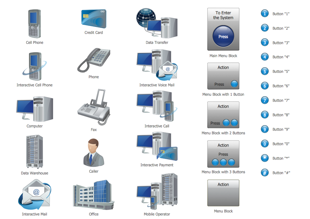
Now you don't need to be an artist to create professional looking and attractive IVR and VoIP diagrams with voice actors. Interactive Voice Response Diagrams Solution offers you the Interactive Voice Response library which contains 35 vector shapes to help you in your drawing process.

Example 2. Interactive Voice Response Diagrams Solution in ConceptDraw STORE
Don't afraid to use also the ready samples and templates as the base for your own Interactive Voice Response and Voice-over-Internet Protocol diagrams and schemes. All they are available from ConceptDraw STORE. We hope you will find the useful for you.

Example 3. IVR Voice Services Diagram
This sample was created in ConceptDraw DIAGRAM using the Interactive Voice Response Diagrams Solution and shows the logical and physical structure of IVR system in the form of IVR Services Diagram. An experienced user spent 10 minutes creating every of these samples.
Use the Interactive Voice Response Diagrams Solution for ConceptDraw DIAGRAM software to create your own professional looking IVR and VoIP diagrams and represent the voice actors quick, easy and effective.
All source documents are vector graphic documents. They are available for reviewing, modifying, or converting to a variety of formats (PDF file, MS PowerPoint, MS Visio, and many other graphic formats) from the ConceptDraw STORE. The Interactive Voice Response Diagrams Solution is available for all ConceptDraw DIAGRAM or later users.
FIVE RELATED HOW TO's:
The ConceptDraw vector stencils library Cisco Security contains 16 symbols of security devices and equipment for drawing the computer network diagrams using the ConceptDraw DIAGRAM diagramming and vector drawing software.
Picture: Cisco Security. Cisco icons, shapes, stencils and symbols
Related Solution:
What is IVR? The Interactive voice response (IVR) is a popular and widely used technology which allows a computer to detect voice and keypad inputs, so it makes possible the interactions between computer and humans through the use of voice and dual-tone multi-frequency (DTMF) signals. For illustrating the logical and physical structure of IVR systems are used the IVR diagrams. ConceptDraw DIAGRAM software extended with Interactive Voice Response Diagrams solution allows you to make the IVR Diagrams quickly and easily.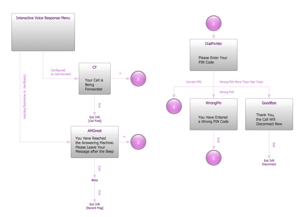
Picture: What is IVR?
Related Solution:
A network diagram represents the set of computers and network devices and the connections among them. This scheme can be developed for any institution or establishment. To illustrate this concept let’s take for example, a hotel network topology diagram or a school network diagram. These diagrams depict access points, servers, workstations, firewalls and another equipment needed to provide a network.
On this masterpiece drawing one will see a simple scheme a of connecting computers together. Such form of connecting can be applied for a hotel, guest house, bungalow, hut or something else. This diagram shows the images of the real LAN components. So, it represents a physical category of a network construction. It looks similar to a star - so this network configuration is named a star topology. The typical feature of this construction is a center point - usually it is hub, or router. The rays of this star means network connections. Computers, peripherals and other network details are placed on the ends of the star rays.
Picture: Hotel Network Topology Diagram
Related Solution:
Why do you need network visualizations? 🔸 Unlock the full potential of network visualization with our in-depth guide on using the ConceptDraw Network Visualization Tool. ✔️ Explore features, tips, and best practices to create stunning visual representations of your network architecture
Picture:
Network Visualization Guide.
How to Use ConceptDraw Network Visualization Tool
Related Solutions:
Communication via Internet nowadays is almost irreplaceable part of lifestyle. It’s needless to say that providing that communication is not a piece of cake, and network diagram software is useful for representing all the interconnections between network devices. These diagrams are also helpful for educational purposes.
This drawing depicts the network topology of the sample web studio. This is a physical type of network diagram. It is depicting the network, end-user equipment and connections between them. The given network has combined the both star and mesh network topology features. This diagram is a tool of network administrator. it delivers the actual information on location of servers, hubs, switches, routers, and other telecommunication equipment. The collection of network related symbols provided with ConceptDraw Network Diagrams solution represents the entire network components. All Symbols are standard. Therefore, network specialists can effortlessly decrypt this diagram.
Picture: Network Diagram Software
Related Solution:

