Technical Drawings
A technical drawing or a technical drafting is a detailed engineering drawing that shows the information about construction and functioning of some technical object. Technical drawings help to transform an idea or a concept into reality. They are the graphic diagrams used in many technical fields: architectural, mechanical, electrical, aerospace, and many others. They are indispensable in building, design, manufacturing, engineering.
Technical drawings include construction drawings, electrical drawings, wiring diagrams, plumbing drawings, water supply system drawings, HVAC construction drawings, firefighting drawings, equipment schematic drawings, and many others. They are essential for many specialists at all stages: architects, contractors, engineers, mechanics, construction personnel, surveyors, electricians, plumbers, telecommunication specialists, and many other technical specialists to develop, construct, commission, or repair objects, mechanisms, buildings, etc.
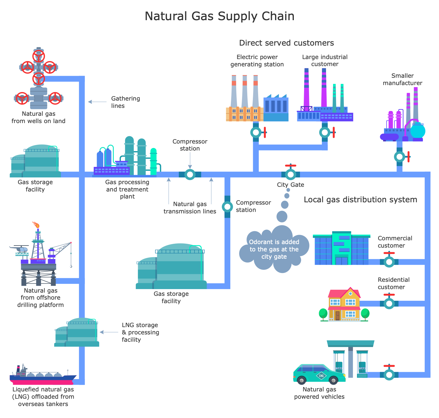
Technical drawings are convenient to communicate ideas and include important technical information to develop mechanisms, constructions, etc. They are essential in public utilities supply, water, gas, and electricity supply chain. It is a way of communication between designers and engineers, who imagine new projects and technologies, and also people who have interesting ideas but have no technical education with people who can implement these ideas.
A technical drawing provides information clearly and concisely, it includes construction details, dimensions, notes, specifications, annotations to represent and explain the purpose of the system's components, helps to plan and document works, outlines equipment and materials. It is an instruction on how to manufacture a certain product, construct an object, build a building, fabricate or assemble something, install or repair a system, etc. Technical drawings show the dimensions, geometry of parts, and give an overview of functions and crucial features. They also easier the cost estimation. Each detail has value, units of measurement, notation, and many more details. Therefore creating technical drawings requires special attention and accuracy.
Technical draftings are made at a precise scale. Precision and unambiguity are the main and really important characteristics of any technical drawing. The internationally accepted rules, symbols, icons, notation systems, designations are used in technical documentation. This makes it easily understandable for all experts in a specific area, engineers, architects, contractors, and other stakeholders. The indication of measurement units and perspectives makes technical drawings clear, detailed, and uniquely interpreted.
Example 1. Technical Drawings Design in ConceptDraw DIAGRAM
You can create your technical drawings by hand on paper, but the use of professional software to create them in electronic form is preferable. Special professional ConceptDraw DIAGRAM charting and vector drawing software helps to automate and easier drawing process, saves time and effort. It is an indispensable tool for design engineers, architects, technical draftsmen, and many other professionals to create detailed technical documentation, technical drawings, engineering draftings, and sketches at different stages of manufacturing.

Example 2. Public Utilities Libraries Design Elements
Public Utilities solution from the Management area of ConceptDraw Solution Park offers a number of professional drawing tools and vector stencils to construct technical drawings in public utilities area fast and easily. It provides a set of 12 libraries with 188 vector graphics icons:
- Public Works
- Public Education
- Public Healthcare
- Public Spaces
- Public Transit
- Public Security
- Electricity Supply
- Water and Sewage
- Gas Service
- Central Heating
- Traffic Management
- Transport Asset Management

Example 3. Cold District Heating Network
The Public Utilities Infographics samples you see on this page were created in ConceptDraw DIAGRAM software using the drawing tools of the Public Utilities Solution. These examples successfully demonstrate solution's capabilities and the professional results you can achieve using it. An experienced user spent 10-15 minutes creating each of these samples.
Use the powerful tools of the Public Utilities solution to design your own Public Utilities Infographics quick, easy, and effective.
All source documents are vector graphic documents. They are available for reviewing, modifying, or converting to a variety of formats (PDF file, MS PowerPoint, MS Visio, and many other graphic formats) from the ConceptDraw STORE. The Public Utilities Solution is available for ConceptDraw DIAGRAM users.